Method for constructing antennas from textile fabrics and components

Inactive Publication Date: 2005-10-27
APPLIED RADAR
View PDF18 Cites 94 Cited by
  • Summary
  • Abstract
  • Description
  • Claims
  • Application Information

AI Technical Summary

Benefits of technology

[0020] It is a further object of this invention to provide a method of constructing antennas providing for reduced vibration and sound transmission.
[0021] It is a further object of this invention to provide a method of constructing antennas with improved resistance to degradation due to exposure to terrestrial and space environments containing atmospheric oxygen, thermal transients, ultraviolet light

Problems solved by technology

If incorporated into ordinarily flexible fabric articles, such as wearable clothing, tote bags, or vehicle covers, a rigid PCB antenna would create undesirable rigid portions, tending to form objectionable lumps that would be uncomfortable in clothing, and would cause increased fabric wear, reducing article lifetimes and limiting applications.
Rigid PCB antennas are also unsightly without added encumbering packaging and are considered unacceptable for many applications, indoor and outdoor.
Other problems inherent in the use of PCB antennas are as follows.
A conventional PCB antenna can deform under heat and can transmit excessive levels of acoustic noise and vibration.
Further, conventional PCB techniques employ environmentally hostile etching or time-consuming milling steps to implement the desired waveguide patterns into the metal foil.
There are applications for the incorporation of antennas into airframes, ship superstructures or composite support beams for buildings for which conventional PCB techniques are not suitable, due to structural weakening

Method used


Image

  • Method for constructing antennas from textile fabrics and components
  • Method for constructing antennas from textile fabrics and components
  • Method for constructing antennas from textile fabrics and components

Examples


Embodiment Construction

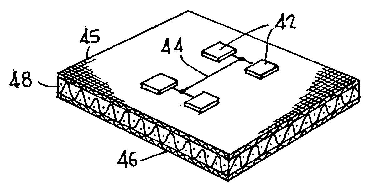
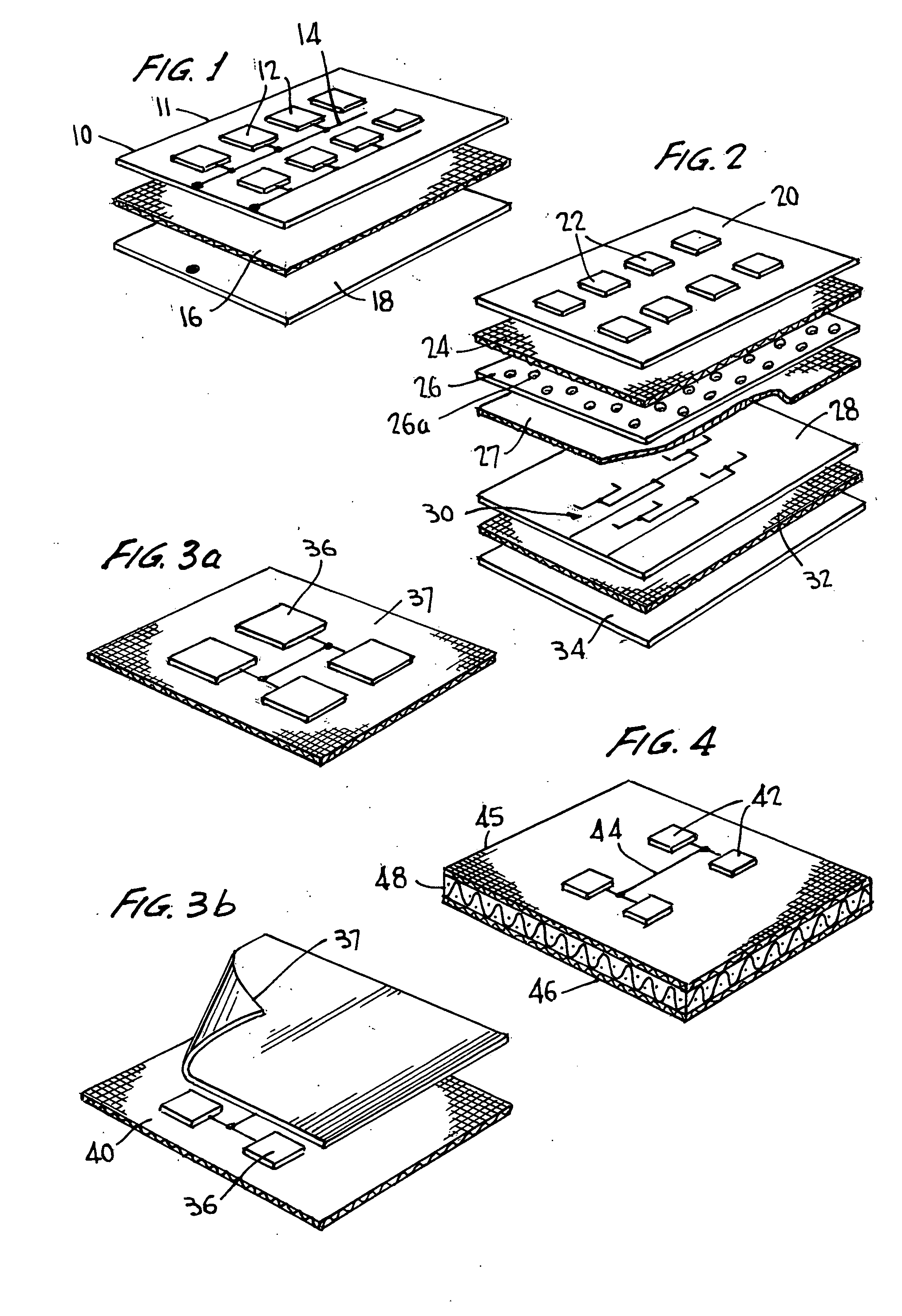
[0044]FIG. 1 shows one embodiment of a three-layer microstrip microwave array antenna according to the invention. A first layer 10 comprises a retention fabric 11 on which conductive patch antennas 12 and feed lines 14 are disposed. These elements may be fabricated of conductive thread, stitched to form the desired patterns, or comprise metallized fabric cut to form the desired patterns. A second spacer fabric layer 16 provides the necessary dielectric material spacing the first layer from a third layer 18, comprising a conductive metallized fabric, which serves as the ground plane, that is, the antenna waveguide boundary. The feed lines and ground plane can be connected to the associated electronics using techniques discussed below.

[0045] Examples of the metallized fabric that can be used as the ground plane and to form the patch antenna elements and feed lines are ShieldEx RTFK 151G; 3M Conductive Copper Impregnated Polyester Tape; 100 Count, 46 Ga. woven copper cloth; Graphite f...


PUM

PropertyMeasurementUnit
Electrical conductivityaaaaaaaaaa
Flexibilityaaaaaaaaaa
Transmissionaaaaaaaaaa

Abstract

Antennas are fabricated using fabric substrates, and, in some embodiments, known stitching techniques to fabricate the conductive members required, including connecting wiring and radiating and/or receiving elements. In one embodiment, one or more “patch antennas”, that is, planar radiating and/or receiving elements, are connected to transmitting and/or receiving electronics by means of a connector and feed line structure. The antenna structure comprises multiple layers of fabric, some of which may contain patch antenna and/or feedline patterns made of conductive fabric, made by embroidery using conductive thread or yarn, or onto which patch antennas may be bonded. A ground plane layer may be fabricated similarly. Between the fabric layers containing the conductive patterns, there are one or more layers of insulating fabrics that separate the conductive fabric layers by a dielectric layer. Additional sheets of adhesive between the fabric layers may be used to attach the fabric layers. Alternatively, stitching of insulating thread can be used to attach the multiple fabric layers together. Conductive thread may be used where a connection is desired, that is, the microwave antenna may include a “via” (an interlayer electrical connection) of conductive thread sewn through insulating fabric layers to connect one or more conductive components, typically of conductive fabric. The antenna may be flexible, so as to be used on clothing and the like, or may be impregnated with a curable resin, for forming a rigid structure for incorporation into a larger structure.

Description

CROSS-REFERENCE TO RELATED APPLICATIONS [0001] This application claims priority from Provisional Application Ser. No. 60 / 557,431, filed Mar. 29, 2004.FEDERALLY SPONSORED RESEARCH [0002] This invention was made in the course of work conducted under contract to the United States Government, under contracts DAAH01-02-C-R128 and DMH01-03-C-R200.FIELD OF THE INVENTION [0003] This invention relates to methods of constructing antennas; it is disclosed in connection with microwave-frequency antennas in particular, as those are of primary interest, but is not limited thereto. BACKGROUND OF THE INVENTION [0004] Numerous microwave communications and sensing devices require an antenna for signal transmission and reception. At microwave frequencies of one GHz or more, multilayer microstrip antennas are commonly employed. These antennas may be single or multi-patch antennas which provide energy transmission or reception in many directions simultaneously. To focus the energy, an array of patch ant...

Claims


Application Information

Patent Timeline
IPC IPC(8): H01P11/00H01Q9/04
CPCH01P11/00Y10T29/49016Y10T29/49018H01Q9/0407
Inventor DEAETT, MICHAEL A.WEEDON, WILLIAM H. III
Owner APPLIED RADAR
Why Eureka
Try Eureka