Movable lens beam steerer

Inactive Publication Date: 2005-10-27
INTEL CORP
View PDF3 Cites 2 Cited by
  • Summary
  • Abstract
  • Description
  • Claims
  • Application Information

AI Technical Summary

Problems solved by technology

Optoelectronics packaging is one of the most difficult and costly operations in optoelectronics manufacturing.
Process manufacturing like submicron alignment between optical elements, high speed electrical connections, excellent heat dissipation, and high reliability present a myriad of challenges.
In the case of optoelectronic module, it is difficult to align a laser diode with the optical lens and fiber, especially during construction of the package.
Current designs use numerous parts in complex three dimensional arrangements and need high degree of accuracy and automation.
Today, virtually a standard of the optoelectronic industry, very costly and very big laser welding stations, that literally takes up the space of an entire standard office, are employed to carry out the optical alignment of these components.
Nevertheless, the welding process often causes a shift to occur in the structure being welded, due to shrinkage of the molten weld material while it is solidifying.
Further, even though a component may be aligned prior to welding, the alignment may nevertheless be off after welding, as the welding process itself may shift the components.
Moreover all subsequence assembly operations can also cause misalignment to the optical train by mishandling, thermal treatment, shock, vibration, and so forth.
Where micron accuracy is needed, these shifting during the welding process affect the overall yield of manufacturing.

Method used


Image

  • Movable lens beam steerer
  • Movable lens beam steerer
  • Movable lens beam steerer

Examples


Embodiment Construction

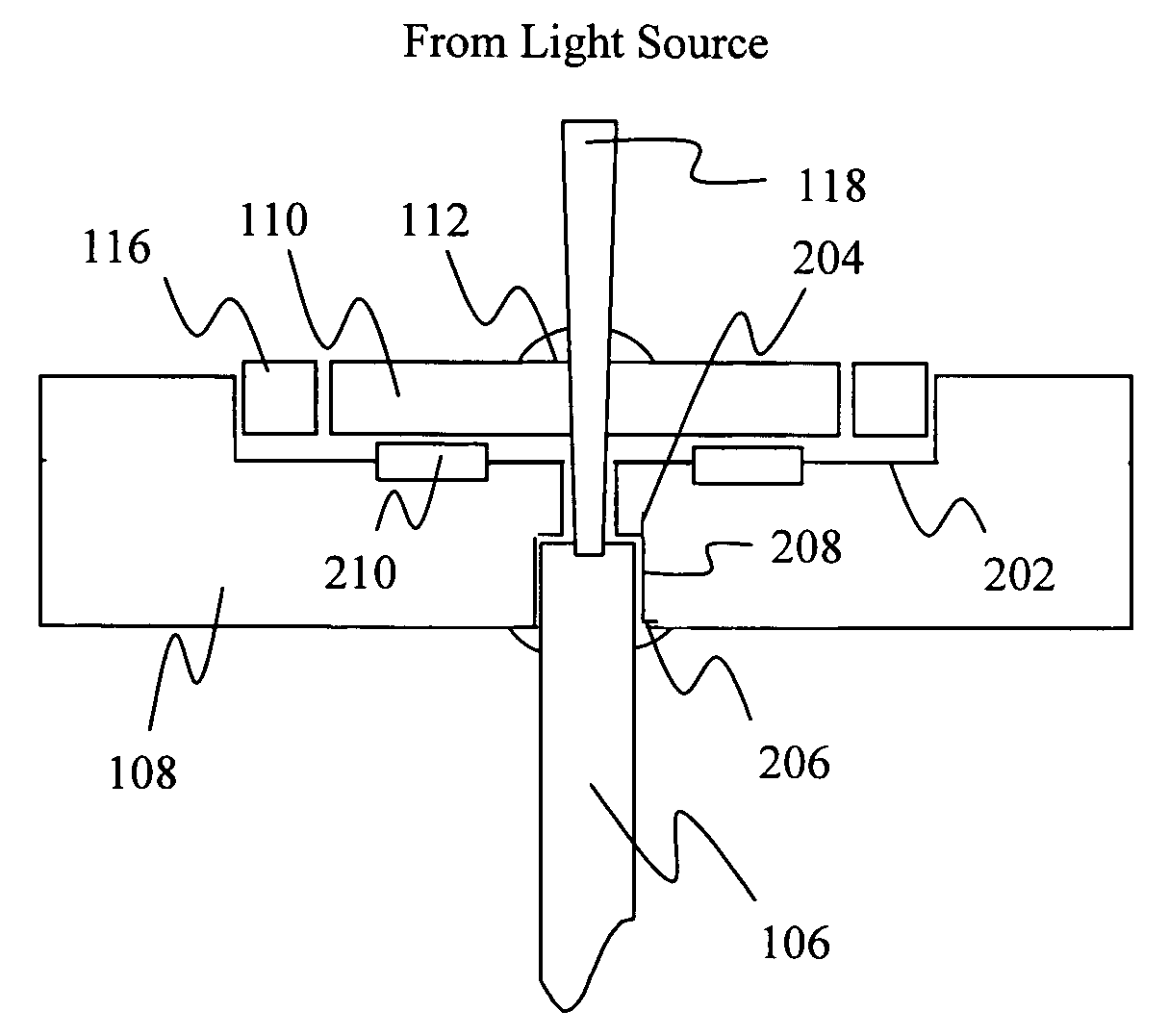
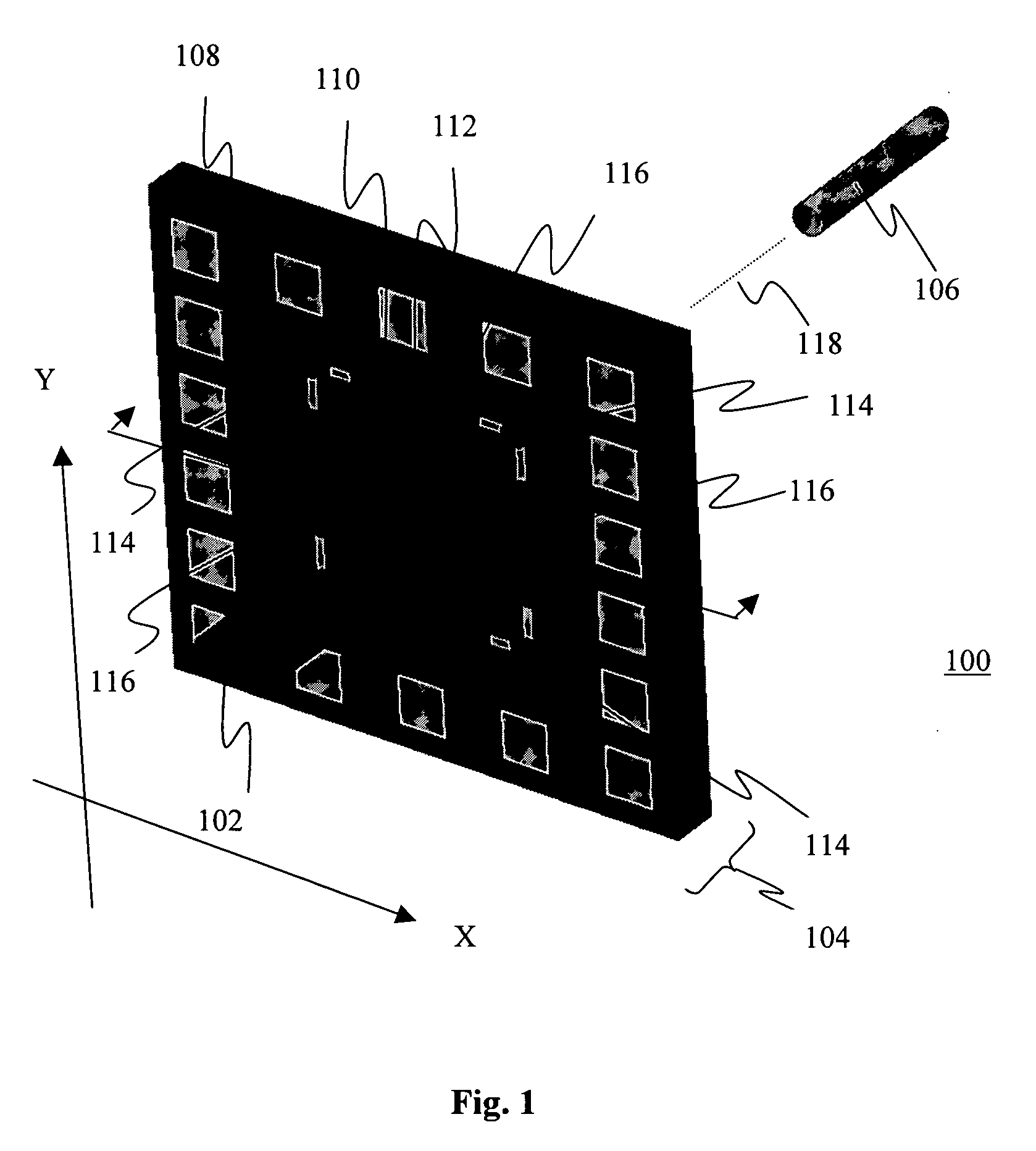
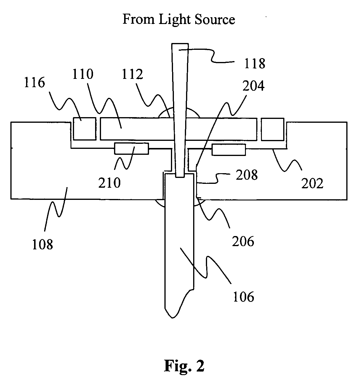
[0012] Illustrative embodiments of the present invention include, but are not limited to, a lens positioning / beam steering arrangement and method, an optoelectronic module equipped with such capability, and a system having such an optoelectronic module.

[0013] Various aspects of the illustrative embodiments will be described using terms commonly employed by those skilled in the art to convey the substance of their work to others skilled in the art. However, it will be apparent to those skilled in the art that the present invention may be practiced with only some of the described aspects. For purposes of explanation, specific numbers, materials, and configurations are set forth in order to provide a thorough understanding of the illustrative embodiments. In particular, various elements of the embodiments will be described at a micro scale level. However, it will be apparent to one skilled in the art that the present invention may be practiced without the specific details and / or at di...


PUM


Abstract

Embodiments of a method to move a lens of an optoelectronic moduleto adjust steering of a light beam, and a system having the optoelectronic module, are described herein.

Description

FIELD OF THE INVENTION [0001] The present invention relates generally to the field of optoelectronic, and in particular, to optoelectronic modules (e.g. transmitter or receiver) with a microlens positioner / beam steerer. BACKGROUND OF THE INVENTION [0002] Optoelectronic applications often have a need to steer a light beam or light bundles to a target. The target may e.g. be a location of an optically readable medium of an optoelectronic read / write device, or a location of an optical fiber of an optoelectronic transmitter / receiver module. Currently, the latter is typically performed at the time of packaging. [0003] Optoelectronics packaging is one of the most difficult and costly operations in optoelectronics manufacturing. Process manufacturing like submicron alignment between optical elements, high speed electrical connections, excellent heat dissipation, and high reliability present a myriad of challenges. [0004] In the case of optoelectronic module, it is difficult to align a lase...

Claims


Application Information

Patent Timeline
IPC IPC(8): G02B6/26G02B6/42G02B7/00G02B26/08
CPCG02B6/4204G02B26/0875G02B7/005G02B6/4226
Inventor EPITAUX, MARCNOELL, WILFRIEDPETREMAND, YVESDE ROOIJ, NICOLAAS-F.
Owner INTEL CORP
Why Eureka
Try Eureka