

Controller for automatic transmission
a technology of automatic transmission and controller, which is applied in the direction of electric control, machines/engines, transportation and packaging, etc., can solve the problems of shortening the time required for the shift, generating a shift shock, and reducing the accuracy of the transmission, so as to achieve the effect of increasing control and high accuracy
- Summary
- Abstract
- Description
- Claims
- Application Information
AI Technical Summary
Benefits of technology
Problems solved by technology
Method used
Image

Examples
first embodiment
[0076] A first embodiment of the present invention will be described below with reference to FIGS. 1 to 20.
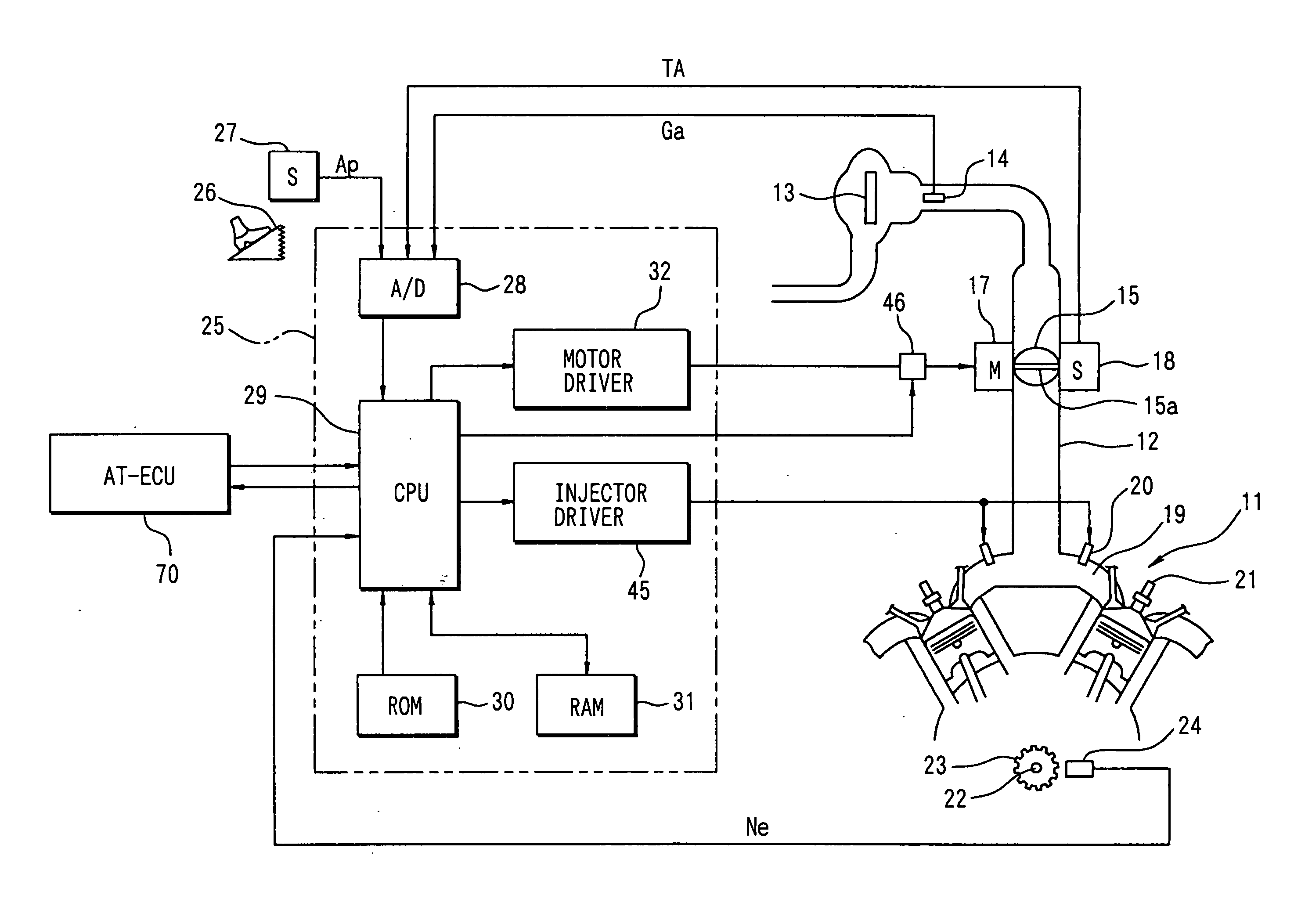
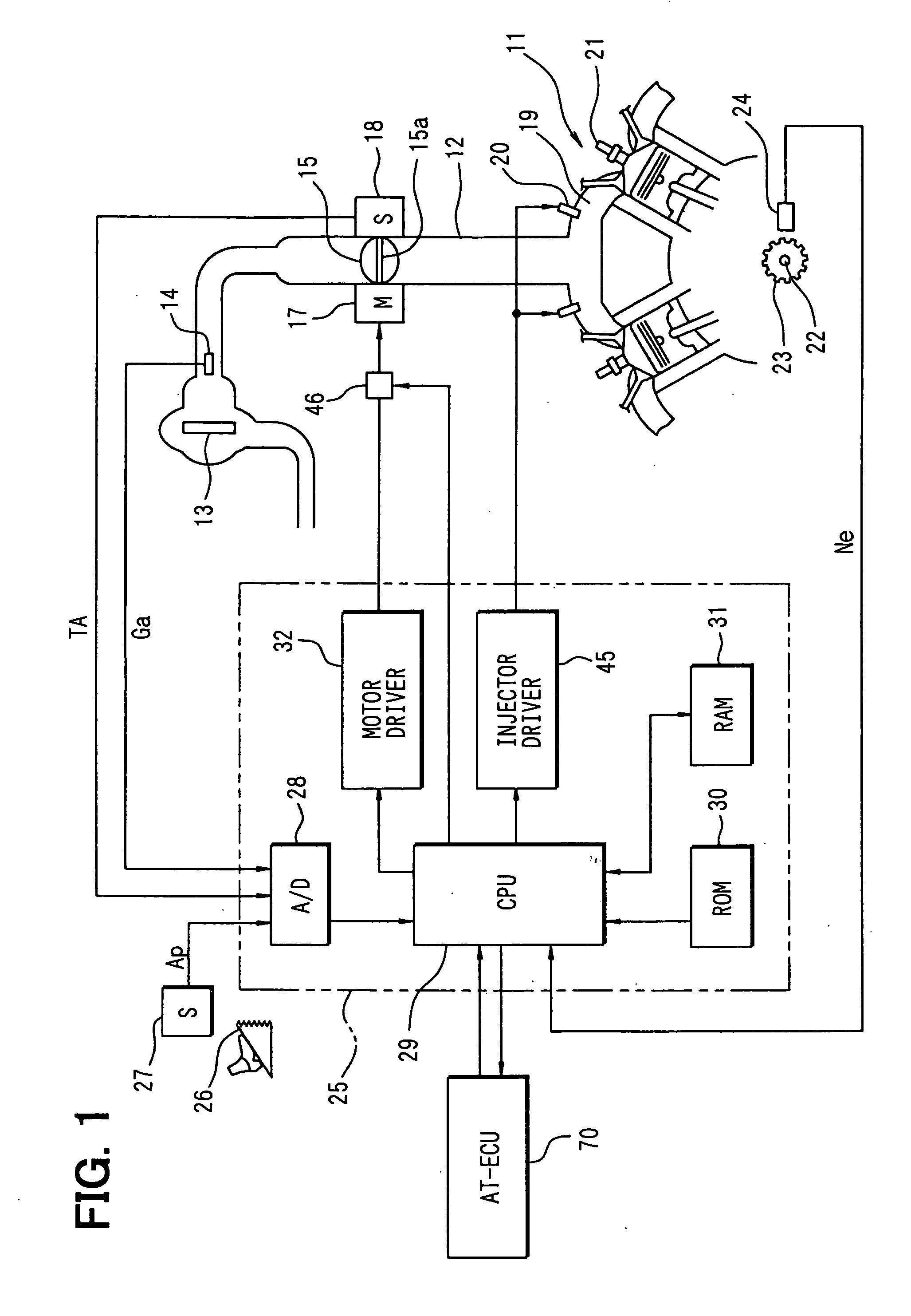
[0077] First, a schematic construction of the whole of a control system for an engine 11 as an internal combustion engine will now be described with reference to FIG. 1. An air cleaner 13 is mounted upstream of an intake pipe 12 of the engine 11, and an air flow meter 14 (intake air quantity detecting means) for measuring an intake air quantity Ga is mounted downstream of the air cleaner 13. Further, a throttle valve 15 is disposed downstream of the air flow meter 14. A motor 17 such as a DC motor is connected to a pivot shaft 15a of the throttle valve 15. The degree of opening (throttle angle) of the throttle valve 15 is controlled with a drive force of the motor 17 and is detected by a throttle angle sensor 18.
[0078] An injector 20 is attached to an intake manifold 19 which introduces intake air having passed through the throttle valve 15 into each cylinder in the engine 11...
second embodiment
[0192] Thus, in the above first embodiment the response of a real oil pressure relative to the oil pressure command value of the releasing clutch is approximated by the transfer characteristic “first order lag+time delay” and the real oil pressure of the releasing clutch is calculated by the weighted averaging calculation based on the oil pressure command value. But in a second embodiment of the present invention, which is illustrated in FIG. 21, attention is paid to the existence of a correlation between an electric current value of an oil pressure control valve (electromagnetic valve) for controlling the oil pressure of the releasing clutch and the amount of operation, and hence oil pressure, of the oil control valve, then the response of a real oil pressure relative to a detected electric current value of the oil pressure control valve is approximated by the transfer characteristic “first order lag+time delay” and a real oil pressure of the releasing clutch is calculated by the w...
third embodiment
[0200] In the above first and second embodiments, at the time of performing ETC cooperation down-shift in accordance with the driver's intention of deceleration, a start timing of the engine output increasing control (throttle opening control and fuel injection return control) is set equal to the time point when the estimated real oil pressure value PrealF decreases to an initial oil pressure (a predetermined transfer torque capacity-equivalent oil pressure). But in a third embodiment of the present invention illustrated in FIGS. 22 to 31, at the time of performing ETC cooperation down-shift, a start timing of the engine output increasing control (throttle opening control and fuel injection return control) is set to the earliest one of the following three time points T1, T2 and T3:
[0201] (1) a time point T1 at which it is determined that the oil pressure of the releasing clutch has decreased to an initial oil pressure (a predetermined transfer torque capacity-equivalent oil pressur...
PUM
 Abstract
Description
Claims
Application Information