
Multi-frequency heat treatment of a workpiece by induction heating

Inactive Publication Date: 2005-11-10
INDUCTOHEAT INC
View PDF5 Cites 16 Cited by
  • Summary
  • Abstract
  • Description
  • Claims
  • Application Information

AI Technical Summary

Benefits of technology

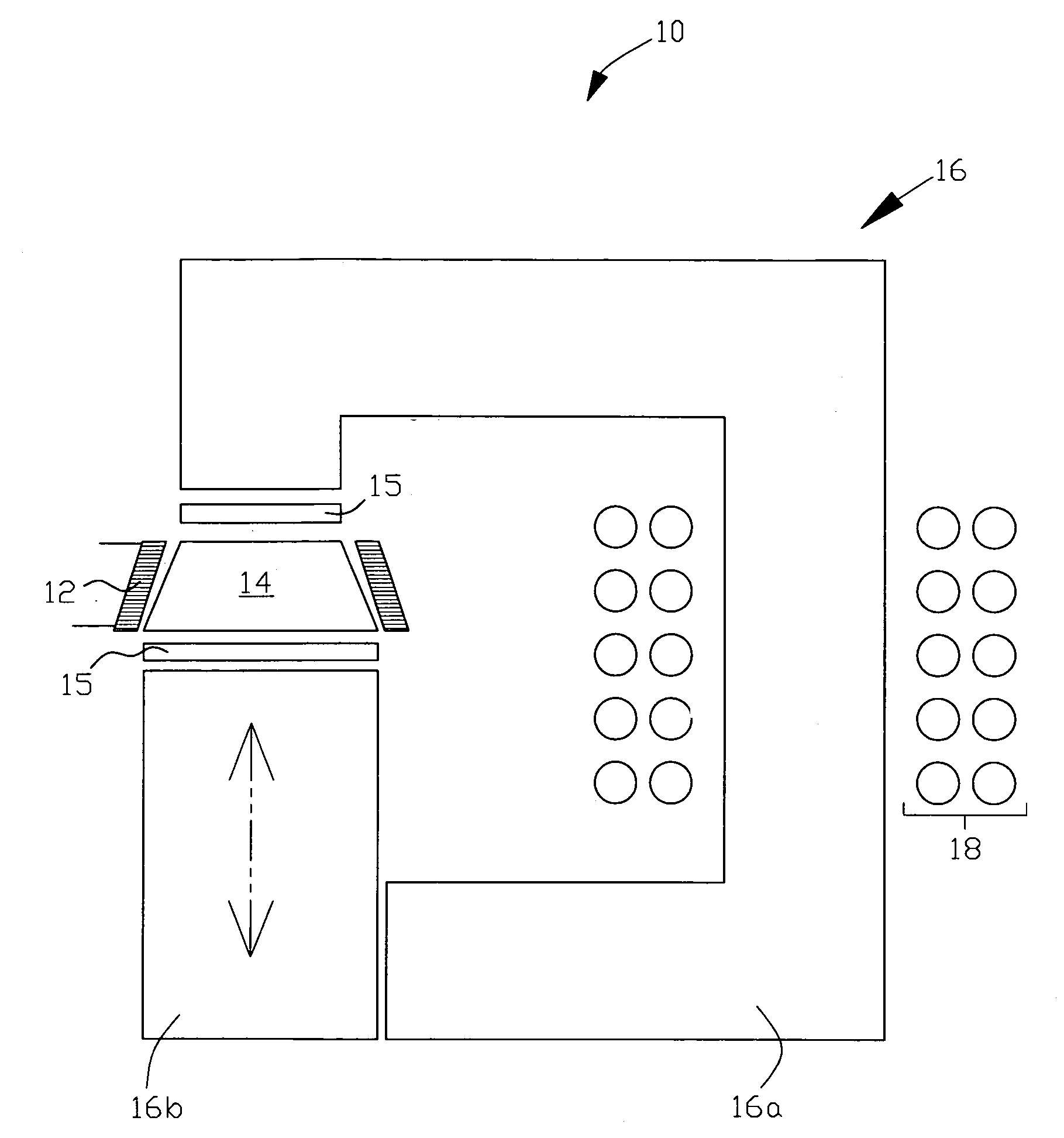
[0011] In one aspect, the present invention is an apparatus for, and method of, heat treating a workpiece by using a combination of two different types (configurations) of induction coils. The workpiece is inductively heated by a first ac current flow through a first induction coil that surrounds the workpiece. The first ac current establishes a magnetic field that inductively couples with the workpiece. The workpiece is also heated by placing the workpiece in an opening in a low frequency C-core type inductor that is coupled to a second induction coil that represents a primary winding. The second induction coil is connected to a second ac current source. The magnetic flux generated by the primary winding flows through the C-core (that acts as a magnetic flux diverter) and also through the workpiece. This

Problems solved by technology

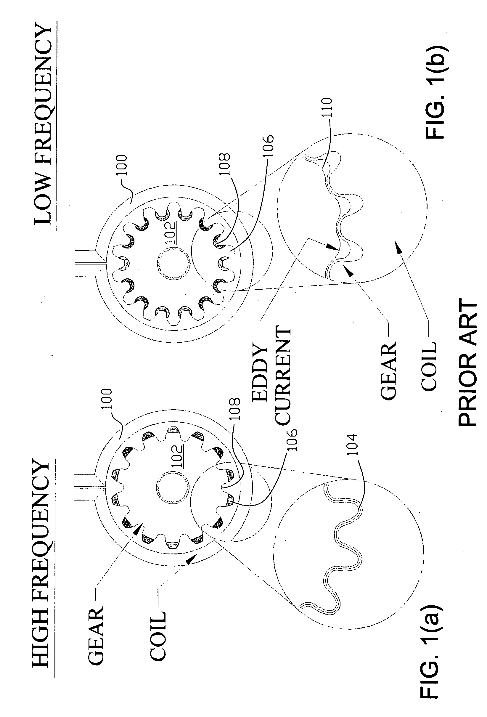
This results in a drastically reduced amount of induced eddy current in the C-core compared to the eddy current induced within the workpiece, and consequently, more intense heating of the workpiece than the C-core.

Method used


Image

  • Multi-frequency heat treatment of a workpiece by induction heating
  • Multi-frequency heat treatment of a workpiece by induction heating
  • Multi-frequency heat treatment of a workpiece by induction heating

Examples


Embodiment Construction

[0024] There is shown in FIG. 4 one example of the induction heat treating apparatus 10 of the present invention. While workpiece 14 illustrated in FIG. 4 is diagrammatically represented as a pinion gear, the induction heat treating apparatus of the present invention is also applicable to other types of gears, and other types of electrically conductive workpieces. High frequency (HF) solenoidal coil 12 at least partially surrounds workpiece 14. Coil 12 may be a single or multi-turn coil. Low frequency C-core inductor 16 comprises a stationary core segment 16a and moveable core segment 16b. The low frequency core may be formed from magnetic materials known in the art, such as a laminated magnetic material, or a powder-based magnetic material, such as a ferrite or iron based material. Low frequency (LF) solenoidal coil 18 surrounds a portion of stationary core segment 16a.

[0025] HF solenoidal coil 12 is suitably connected to a power source of high frequency current (not shown in the ...


PUM

PropertyMeasurementUnit
Frequencyaaaaaaaaaa
Frequencyaaaaaaaaaa
Frequencyaaaaaaaaaa

Abstract

An apparatus and process are provided for multi-frequency induction heat treatment of workpieces including gears. High frequency power is applied to an induction coil that surrounds the workpiece so that a high frequency magnetic field couples with the workpiece to inductively heat the workpiece. A C-core inductor is coupled to a coil that has low frequency power applied to it. The workpiece is inserted in a gap in the C-core inductor magnetic circuit so that it experiences low frequency Joule effect heating when the low frequency current is applied to the coil coupled with the C-core inductor. Alternatively the workpiece may be inserted around the C-core inductor when the workpiece has an opening.

Description

CROSS REFERENCE TO RELATED APPLICATIONS [0001] This application claims the benefit of U.S. Provisional Patent Application Ser. No. 60 / 564,083 filed Apr. 21, 2004, hereby incorporated herein by reference in its entirety.FIELD OF THE INVENTION [0002] The present invention relates to heat treatment of an electrically conductive workpiece wherein a combination of two distinct forms of induction heating at different frequencies is used to accomplish the heat treatment. BACKGROUND OF THE INVENTION [0003] A gear, or other workpiece, may be inductively heat treated by passing an ac current through an induction coil. The current creates a magnetic field around the coil that magnetically couples with the gear to induce eddy current in the gear. Induction hardening of gears provides a martensitic layer at the tooth surface of the gear to increase hardness and wear resistance while allowing the remainder of the gear to be unaffected by the process. The increase in hardness also improves contact...

Claims


Application Information

Patent Timeline
IPC IPC(8): C21D1/42C21D9/32C21D9/60H05B6/10H05B6/36H05B6/40
CPCC21D1/42C21D9/32H05B6/40H05B6/36C21D9/60Y02P10/25H05B6/10H05B6/16B23K13/01
Inventor LOVELESS, DON L.RUDNEV, VALERY I.
Owner INDUCTOHEAT INC
Learn More