Threaded joint for steel pipes

a technology for steel pipes and threaded joints, which is applied in the direction of hose connections, screw threaded joints, mechanical equipment, etc., can solve the problems of increasing the environmental conditions in which crude oil exploration and production takes place, the inability to resist a large compressive load, and the inability of threads to resist compressive loads, etc., to achieve the effect of reducing the risk of slipping

Active Publication Date: 2005-11-10
VALLOUREC OIL & GAS FRANCE SAS +1
View PDF13 Cites 44 Cited by
  • Summary
  • Abstract
  • Description
  • Claims
  • Application Information

AI Technical Summary

Benefits of technology

[0041] In addition, because the wall thickness of the nose portion can be increased as much as possible, the sealability with respect to external pressure can be greatly increased just by slightly increasing the axial length of the nose portion (referred to below as the nose length).
[0042] Furthermore, the shoulder surface can be e...

Problems solved by technology

However, in recent years, the environments in which exploration and production of crude oil and natural gas take place have been becoming increasingly severe, so special high-performance threaded joints referred to as premium joints are being increasingly used.
Therefore, they cannot resist a large compressive load unless the wall thickness of the shoulder surfaces is large (or unless the stiffness of the shoulders is high).
As the external pressure is increased, a gap forms between the sealing surfaces, resulting in leakage, i.e., a situation in which external fluid enters the inside of a pipe.
If a compressive load is applied to a premium joint in situations such as when OCTG is disposed in a horizontal well or directional well, since most joints have a relatively large gap between the stabbing flanks as is the case with the above-described API buttress thread, the threads have a poor ability to resist compressive loads, so most of a compressive load is borne by the shoulders.
Therefore, if a compressive load equivalent to 40 to 60% of the yield strength of the pipe body is applied, most premium joints undergo considerable plastic deformation of the torque shoulder portion of the box, resulting in a significant reduction in the sealability of the adjacen...

Method used


Image

  • Threaded joint for steel pipes
  • Threaded joint for steel pipes
  • Threaded joint for steel pipes

Examples


examples

[0110] In order to clearly demonstrate the effects of the present invention, numerical simulation analysis by the elastoplastic finite element method was carried out for the specimens shown in Table 1.

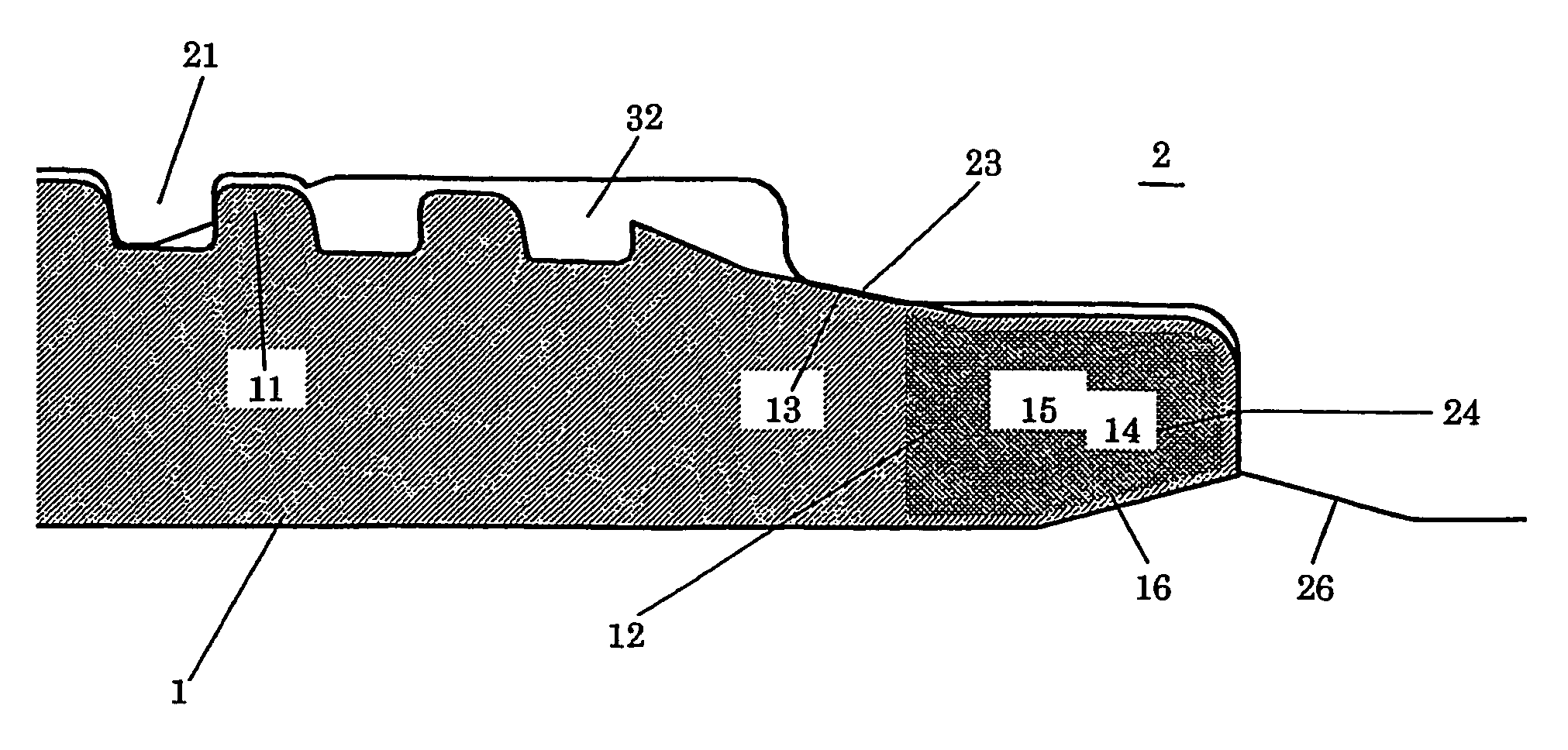
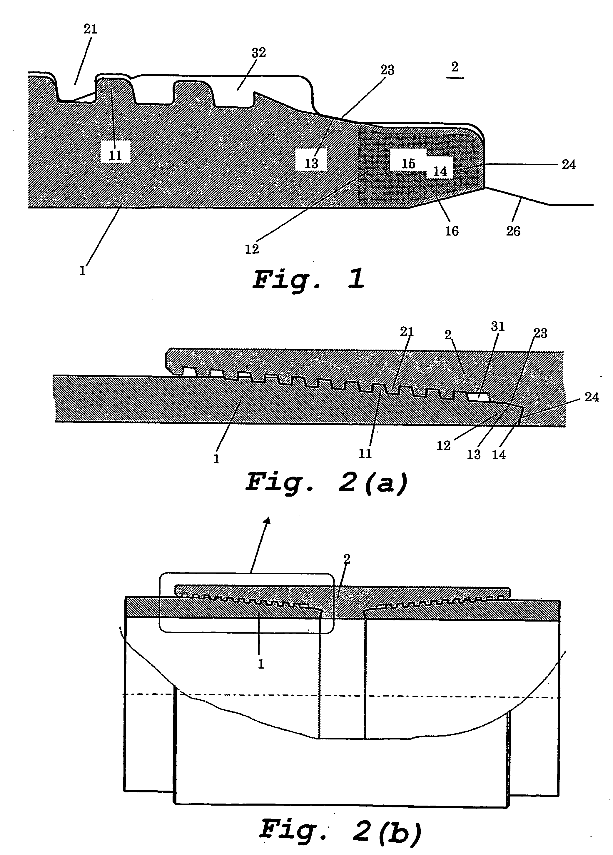
[0111] The specimens shown in Table 1 were all coupling-type threaded joints for OCTG like that shown in FIG. 2 for use with 5- 1 / 2″ 20# (lb / ft) steel pipes (outer diameter of 139.7 mm and wall thickness of 9.17 mm). The steel material used for all the specimens was that specified as P110 by API standards.

[0112] Specimen B was a comparative example in the form of a conventional premium joint. It had a pin lip shape like that shown in FIG. 13. In FIG. 13, reference numbers which are the same as those previously used indicate the same members.

[0113] Specimens C-O had basically the same joint structure as for Specimen A except that the dimensions of the various portions were varied as shown in Table 1.

[0114] However, for Specimen J, the end of a pipe body having the above-described si...


PUM


Abstract

A threaded joint for steel pipes comprises a pin (1) and a box (2). The pin has male thread (11), a sealing surface (13), and a shoulder surface (14) located on the end face of the pin. Correspondingly, the box has female thread (21), a sealing surface (23), and a shoulder surface (24) which can mate or contact with the corresponding portions of the pin. The shoulder surface (14) of the pin (1) is provided at an end face of the pin. The sealing surface (13) of the pin (1) is located on a pipe end side near the male thread (11). A a nose portion (15) is provided on the pin (1) between the sealing surface (13) and the shoulder surface (14), the nose portion (15) being not in contact with a corresponding portion of the box (2).

Description

TECHNICAL FIELD [0001] The present invention relates generally to a threaded joint for use in connecting steel pipes such as oil well pipes or OCTG (oil country tubular goods) including tubing and casing, riser pipes, and line pipes for use in exploration and production of oil wells and gas wells, and particularly to a threaded joint for steel pipes having excellent sealability with respect to external pressure and resistance to compression. BACKGROUND ART [0002] Threaded joints are widely used for connecting steel pipes, such as OCTG and riser pipes for use in industrial oil production equipment. [0003] In the past, standard threaded joints specified by API (American Petroleum Institute) standards have typically been used to connect steel pipes for use exploration and production of oil and gas. However, in recent years, the environments in which exploration and production of crude oil and natural gas take place have been becoming increasingly severe, so special high-performance thr...

Claims


Application Information

Patent Timeline
IPC IPC(8): E21B17/042F16L15/04F16L15/06
CPCE21B17/042F16L15/04F16L15/004
Inventor SUGINO, MASAAKIYAMAMOTO, MIYUKIIWAMOTO, MICHIHIKONAGASAKU, SHIGEODUTILLEUL, PIERREROUSSIE, GABRIELVERGER, ERIC
Owner VALLOUREC OIL & GAS FRANCE SAS
Why Eureka
Try Eureka