Inkjet recording element
a recording element and inkjet technology, applied in the direction of instruments, physical/chemical process catalysts, silicates, etc., can solve the problems of poor image stability in time of printing paper comprising an ink-receiving layer containing such inorganic receivers, loss of color density, etc., to improve dye keeping properties in time and good gloss
- Summary
- Abstract
- Description
- Claims
- Application Information
AI Technical Summary
Benefits of technology
Problems solved by technology
Method used
Image
Examples
example 1
[0062] An aluminosilicate polymer in hollow sphere form was prepared according to the method described in U.S. Pat. No. 6,254,845.
[0063] Sodium orthosilicate was dissolved in purified water to obtain 50 ml of an aqueous solution at 0.1 mol / l. Separately, aluminum chloride was dissolved in purified water to obtain 67.15 ml of an aqueous solution at 0.1 mol / l. The aluminum chloride solution was mixed at high speed with the aqueous solution of sodium orthosilicate. At this stage, the aluminum concentration was 5.7×10⁻² mol / l. The Al / Si molar ratio was 1.34. The mixture was stirred for one hour at ambient temperature. A suspension was obtained that was filtered using a membrane filter to eliminate byproducts such as sodium chloride. The retentate that adhered to the filter was recovered, and 120 ml of purified water was added to it. The mixture was dispersed using ultrasound for one hour and then warmed for five days at 80° C., washed with purified water, and dried in normal conditions...
example 2
[0065] 0.45 moles AlCl3, 6H2O were added to 10 l osmosed water. Separately, a mixture of tetraethyl orthosilicate and methyltriethoxysilane was prepared in a quantity corresponding to 0.25 moles silicon and so as to have a ratio of tetraethyl orthosilicate to methyltriethoxysilane of 1 in moles silicon. This mixture was added to the aluminum chloride solution. The resulting mixture was stirred and circulated simultaneously through a bed formed of 100 g glass beads 2-mm diameter using a pump with output 8 l / min. The operation of preparing the modified mixed aluminum and silicon precursor took 60 minutes. Then, according to step a) of the method for preparing the hybrid aluminosilicate polymer used in the present invention, 1.05 moles NaOH 3M were added in two hours. The reaction medium clouded. According to step b) of the preparation method, the mixture was stirred for 24 hours. The medium became clear. The circulation was stopped in the glass bead bed. Then, according to step d) of ...
example 3
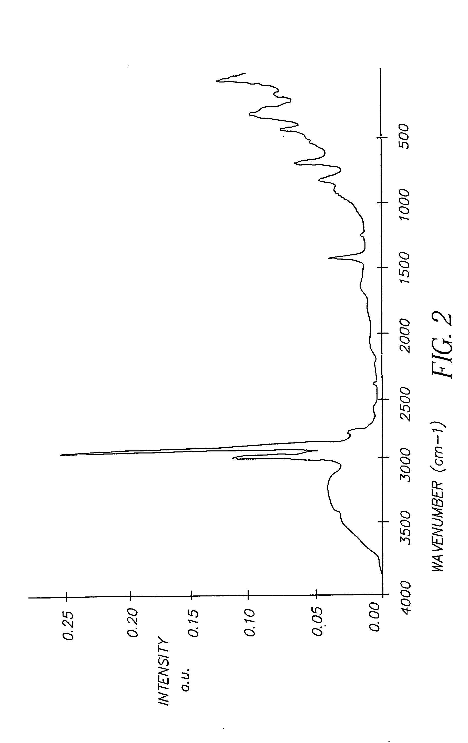
[0067] Example 2 was repeated using, for preparing the modified mixed aluminum and silicon precursor, a mixture of ethanol (3168 g), tetraethyl orthosilicate and 3-chloropropyltriethoxysilane in a quantity corresponding to 0.25 moles silicon and so as to have a tetraethyl orthosilicate / 3-chloropropyltriethoxysilane ratio of 1 in moles silicon. FIG. 3 represents the Raman spectrum of this polymer that was lyophilized to obtain its Raman signature.
PUM
 Abstract
Description
Claims
Application Information
 - R&D
- Intellectual Property
- Life Sciences
- Materials
- Tech Scout
- Unparalleled Data Quality
- Higher Quality Content
- 60% Fewer Hallucinations
Browse by: Latest US Patents, China's latest patents, Technical Efficacy Thesaurus, Application Domain, Technology Topic, Popular Technical Reports.
© 2025 PatSnap. All rights reserved.Legal|Privacy policy|Modern Slavery Act Transparency Statement|Sitemap|About US| Contact US: help@patsnap.com


