System and method for controlling the light source of a cavity ringdown spectrometer

a technology of ring-down spectrometer and light source, which is applied in the field of system and method for controlling the light source of the cavity ring-down spectrometer, can solve the problems of ring-down (exponential decay), affecting the repetition rate and hence measurement speed, and limiting the amount of cavity filling that can be achieved in practice, etc., to achieve the effect of low repetition ra

Inactive Publication Date: 2005-11-17
PICARRO
View PDF5 Cites 55 Cited by
  • Summary
  • Abstract
  • Description
  • Claims
  • Application Information

AI Technical Summary

Benefits of technology

[0034] While this system may sometimes have advantages over a system using an AOM to turn off the light into the optical cavity it is not capable of achieving the deg

Problems solved by technology

Several factors limit how much cavity filling can be achieved in practice.
In addition, filling uniformity also affects the repetition rate and hence measurement speed.
“Turning off” the light into the cavity results in a “ring-down” (exponential decay).
However, this approach must allow the laser emission wavelength to stabilize each time the current into the gain medium is turned back on, which, of necessity, limits the repetition rate of the system.
However, use of an AOM creates a number

Method used


Image

  • System and method for controlling the light source of a cavity ringdown spectrometer
  • System and method for controlling the light source of a cavity ringdown spectrometer
  • System and method for controlling the light source of a cavity ringdown spectrometer

Examples


Embodiment Construction

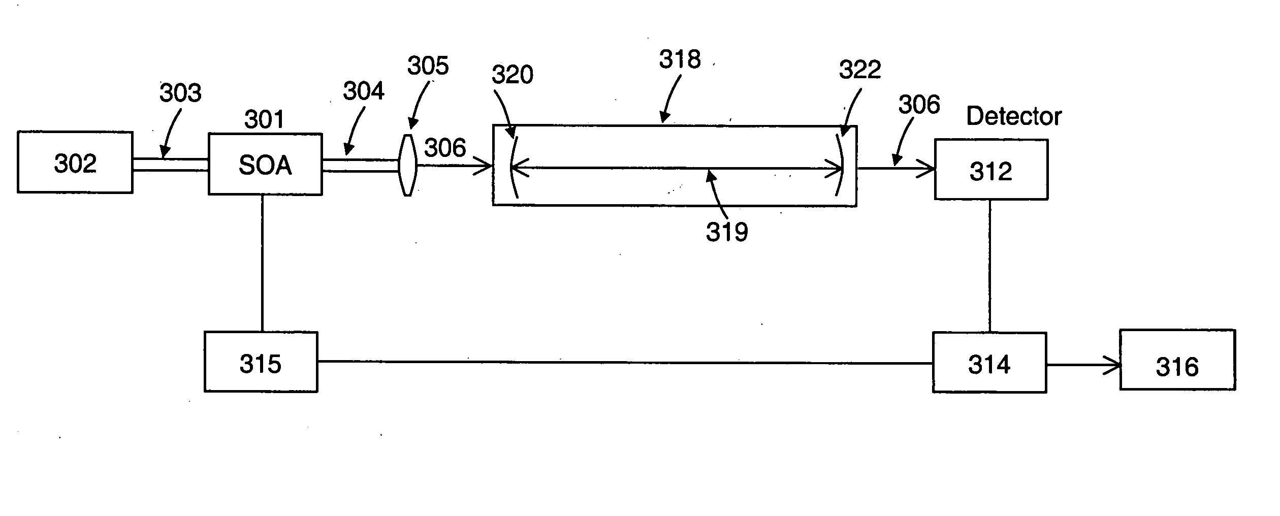
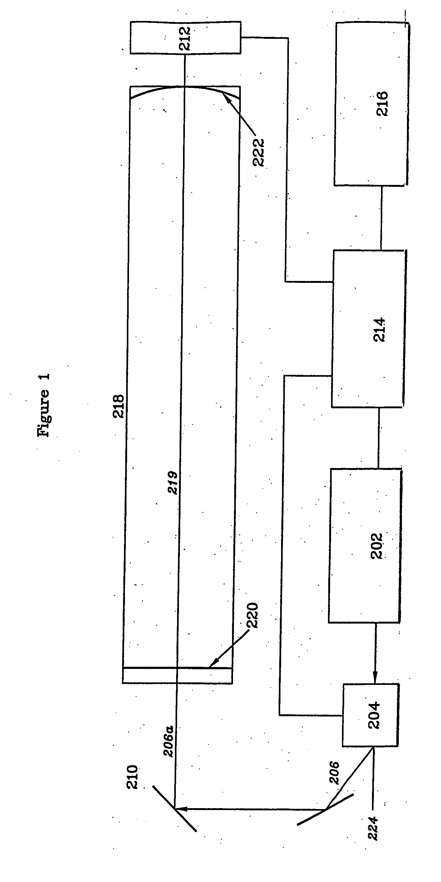
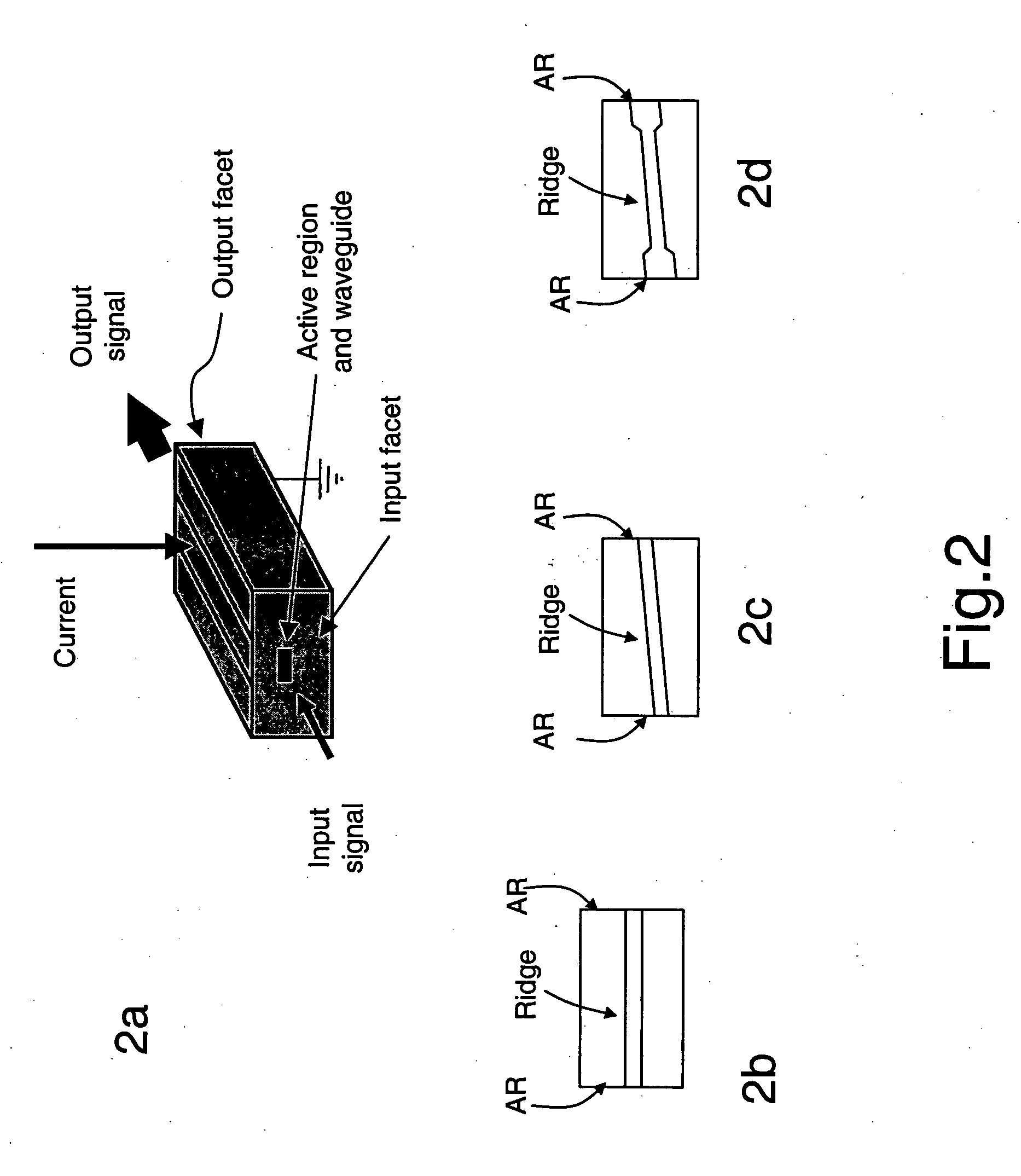
includes passages that are chiefly or exclusively concerned with particular parts or aspects of the invention. It is to be understood that this is for clarity and convenience, that a particular feature may be relevant in more than just the passage in which it is disclosed, and that the disclosure herein includes all the appropriate combinations of information found in the different passages. Similarly, although the various figures and descriptions herein relate to specific embodiments of the invention, it is to be understood that where a specific feature is disclosed in the context of a particular figure or embodiment, such feature can also be used, to the extent appropriate, in the context of another figure or embodiment, in combination with another feature, or in the invention in general.

[0078] Further, while the present invention has been particularly described in terms of certain preferred embodiments, the invention is not limited to such preferred embodiments. Rather, the scope...


PUM


Abstract

A system and method for controlling the light source of a cavity ring-down spectrometer (CRDS). The system comprises a resonant optical cavity having at least two high reflectivity mirrors; a source for providing a continuous wave optical signal into the optical cavity, the source comprising an electrically pumped semiconductor gain medium; and a SOA interposed between the optical signal source and the optical cavity. The SOA receives the optical signal and transmits it to the resonant optical cavity. The system also includes a first detector for monitoring the intensity of radiation emitted from said cavity and generating a first detection signal based thereon; and at least a first controller for deactivating the optical signal based on a comparison of the first detection signal and a predetermined threshold and for thereafter reactivating the optical signal after a delay period in excess of the ring-down time of the optical cavity, the deactivating and reactivating being achieved by respectively turning off and then turning on electrical current to the SOA.

Description

FIELD OF THE INVENTION [0001] This invention relates to cavity ring-down absorption spectroscopy (CRDS). In particular, this invention relates to an apparatus and method for controlling the input of laser light into the resonant optical cavity of a CRDS instrument. BACKGROUND OF THE INVENTION [0002] Cavity Ring-Down Spectroscopy (CRDS) is an increasingly widely used technique for detecting and monitoring analytes, especially when the target analyte is present in very low concentration. Techniques are available which enable the use of CRDS with gaseous, liquid or solid samples. Various aspects of CRDS are described in numerous U.S. Pat. Nos. such as 5,815,277, 5,903,358, 5,912,740, 6,084,682, 6,094,267, 6,233,052, 6,377,350, 6,452,680, 6,466,322 and 6,532,071. Cavity Ringdown Spectroscopy by K. W Busch and M. A Busch, ACS Symposium Series No 720, 1999 ISBN 0-8412-3600-3, gives a comprehensive, and generally up to date, overview of many aspects of CRDS technology. [0003] In essence, C...

Claims


Application Information

Patent Timeline
IPC IPC(8): G01J3/10G01J3/42G01N21/39G01N21/61
CPCG01J3/0205G01J3/0218G01J3/0232G01N2021/399G01J3/10G01J3/42G01N21/39G01J3/0256
Inventor KACHANOV, ALEXANDERPALDUS, BARBARAKOULIKOV, SERGUEI
Owner PICARRO
Why Eureka
Try Eureka