
System and method for time correlated multi-photon counting measurements

a multi-photon counting and counting system technology, applied in the field of time correlated multi-photon counting measurement, can solve the problems of only being able to count tcspc cannot, and the technique is only capable of counting a maximum of one photon

Inactive Publication Date: 2005-11-17
GE HEALTHCARE LTD
View PDF5 Cites 33 Cited by
  • Summary
  • Abstract
  • Description
  • Claims
  • Application Information

AI Technical Summary

Benefits of technology

[0010] Yet another advantage of the invention is to be able to take into account the PMT dead time in the lifetime analysis or any other instrumental parameters, such as e.g non-delta illumination, etc.

Problems solved by technology

In many of these areas, distinguishing the weak but characteristic emission of the substance of interest from background light is difficult.
The technique is only capable of counting a maximum of one photon per excitation.
As above indicated, TCSPC can, even if the mentioned improvements are utilised, be a time consuming measurement.
It is realised in the art that the method is wasteful in that only the first emitted photon is detected and used for the determination of the fluorescence lifetime, even though the subsequently emitted photons carry information useful for the determination of the characteristic lifetime.
The suggested Multiplexed Time Correlated Single-Photon Counting (M-TCSPC)—techniques represent significant improvements over the TCSPC—techniques, but have the drawback that the number of photons that it is possible to detect following one excitation pulse is limited by the number of detectors (or detector elements) used; therefore a large number of excitation cycles is still needed to determine the fluorescence lifetime of the material.
In addition multielement detectors are costly, as are systems providing a large number of single detectors in a multiplexing arrangement
The known apparatus and measurement techniques thus suffer, as above described, from a number of disadvantages and limitations, the most important being the long measurement time.

Method used


Image

  • System and method for time correlated multi-photon counting measurements
  • System and method for time correlated multi-photon counting measurements
  • System and method for time correlated multi-photon counting measurements

Examples


Embodiment Construction

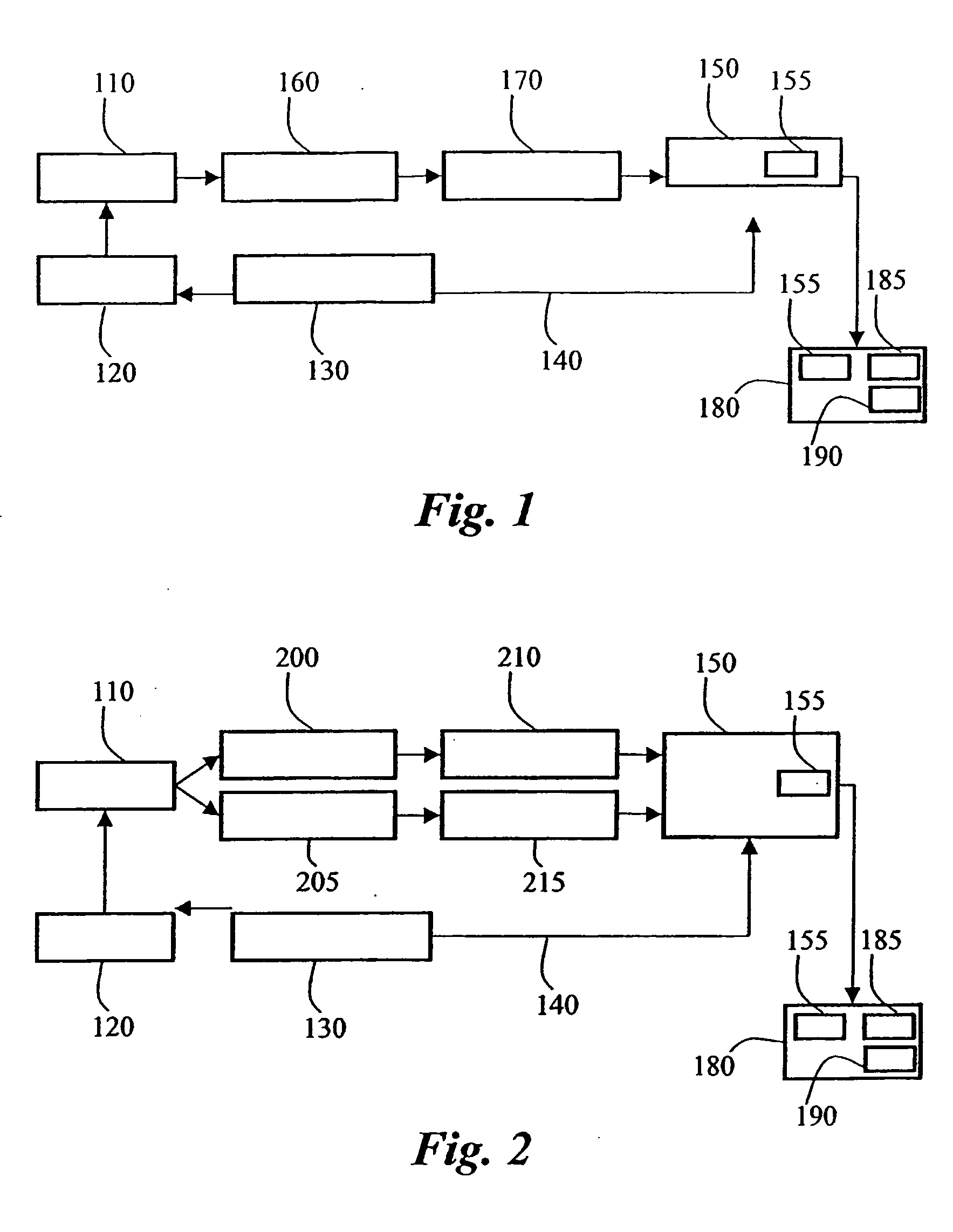
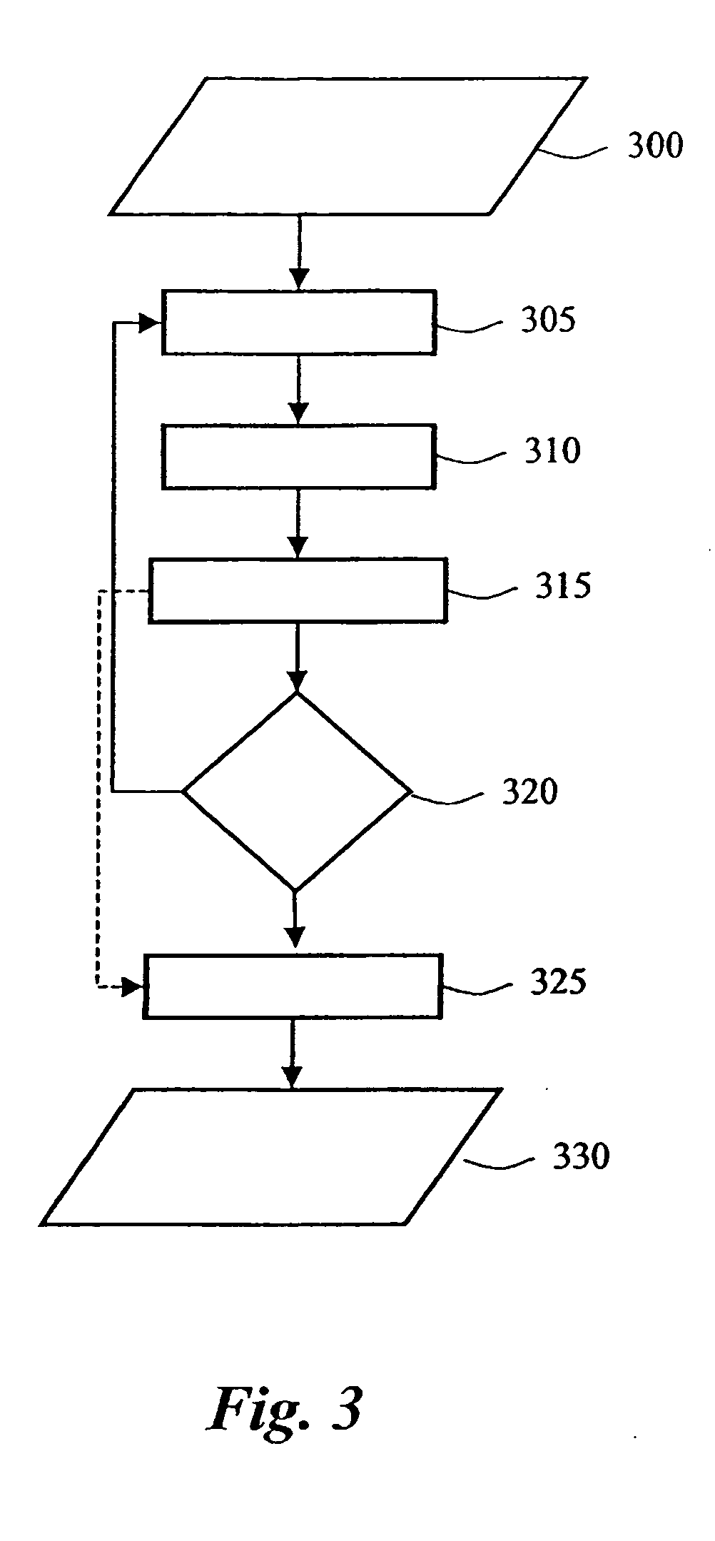
[0020] The inventive measurement system provided by the present invention will be described with reference to the schematic illustrations of FIG. 1-2. FIG. 1 shows a single channel TCMPC system according to the invention. Fluorescent material is contained in a sample 110. An excitation light source 120 for repeatedly irradiating the sample with pulses of excitation light is provided. The light source preferably a pulsed laser. A light source driving and controlling unit 130 comprises the laser power supply and is arranged to generate a triggering signal 140 to a photon timing unit 150. The repetition rate of the excitation light should be sufficiently low to allow a total decay of the fluorescence of the sample before the next exciting pulse. A pulsing frequency of for example around 200 kHz would commonly be appropriate. The duration of the pulse of excitation light should be significantly shorter than the fluorescence lifetime of the fluorophore in order to obtain reliable lifetim...


PUM

PropertyMeasurementUnit
timeaaaaaaaaaa
pulsing frequencyaaaaaaaaaa
fluorescence lifetimeaaaaaaaaaa

Abstract

The invention provides a method and a measurement system for characterisation of luminescence properties, the method comprises irradiating the luminescent material with a pulse of excitation light, providing a triggering signal correlated to the pulse of excitation light; detecting with a photodetector such as a photomultiplier tube (PMT) a plurality of photons emitted from the luminescent material as result of the pulse of excitation light, the photodetector providing an output signal upon the event of detection of a photon; determining for each detected photon a photon arrival time and providing an output suitable for inputting to an analysing module wherein an output comprises zero, one, or more photon arrival time for each excitation, receiving said outputs in an analysing module; and determining. in the analysing module, characteristics properties of the luminescent material by performing a statistical analysis based on Bayesian inference.

Description

[0001] The present invention relates to a method and system for measuring luminescence lifetime. More particularly, the invention relates to a method and apparatus that significantly reduces the measurement time in a Time Correlated Multi-Photon Counting (TCMPC)-measurement. BACKGROUND OF THE INVENTION [0002] Measurement of the luminescence emission of substances has become increasingly important as a sensitive analytical technique in a wide range of disciplines such as chemistry, biology, engineering, materials science and application areas ranging from pollution monitoring and production control in a chemical plant to the sequencing of DNA. In many of these areas, distinguishing the weak but characteristic emission of the substance of interest from background light is difficult. Measuring the lifetime of the light emission of the substance of interest can often be used to discriminate the desired signal from a background. In this context we define the luminescence lifetime of a su...

Claims


Application Information

Patent Timeline
Patent Type & Authority Applications(United States)
IPC IPC(8): G01N21/64
CPCG01N21/6408
Inventor LABARBE, RUDISEWELL, ROGERPUMPHREY, SAM
Owner GE HEALTHCARE LTD
Learn More