Pneumatic tool with integrated electricity generator

a technology of integrated electricity and generators, applied in the direction of electric generator control, magnetic circuit shape/form/construction, magnetic circuit rotating parts, etc., can solve the problems of tool itself placing constraints, machining special rotors in order to accommodate magnets, and time-consuming and accordingly expensive stators

Active Publication Date: 2005-11-24
VOLT AIRE CORP +1
View PDF14 Cites 25 Cited by
  • Summary
  • Abstract
  • Description
  • Claims
  • Application Information

AI Technical Summary

Benefits of technology

[0013] These together with other aspects and advantages, which will be subsequently apparent, reside in the details of construction and operation as more fully hereinafter described and claimed, reference being had to the accompanying drawings forming a part hereof, wherein like numerals refer to like parts throughout.

Problems solved by technology

As would be understood by one of ordinary skill in the art, machining a special rotor in order to accommodate magnets for inducing electricity in a stator can be complex, time-consuming and accordingly expensive.
Furthermore, pneumatic tools having electricity generating capabilities typically require different magnet-side end plates from their conventional counterparts because of the need to accommodate the size and shape of stator coils and possible supporting circuitry.
In addition, size and shape of the tool itself place constraints on the number of windings used for stator coils, the physical placement of supporting circuitry, and location of a pathway for directing generated electricity to its intended load.
As would be understood, stator core permeability, size of coils and amount of magnetic interference each factor into the amount of EMF produced by a generator, while considerations such as component cost, manufacturability and degree of variation from a conventional counterpart all contribute to the overall cost of the tool.

Method used


Image

  • Pneumatic tool with integrated electricity generator
  • Pneumatic tool with integrated electricity generator
  • Pneumatic tool with integrated electricity generator

Examples


Embodiment Construction

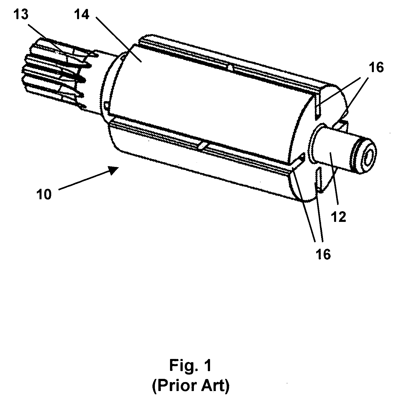
[0030] A conventional pneumatic tool is comprised of a casing onto which is connected a fluid hose. The fluid hose conducts compressed fluid, such as air, from a source through the casing of the tool, causing a rotor within the motor housed by the casing to rotate by effecting force on vanes on the rotor. The rotor, in turn, causes force to be transmitted from a pinion on the rotor through planetary gearing, to drive a ratchet of a wrench, abrasive disk of a grinder etc. at a working end of the tool. While some pneumatic tools make use of gearing in order to transmit rotational force to the working end of the tool, others do so simply by employing a threaded shaft and a collet, or other means appropriate to the primary application of the tool.

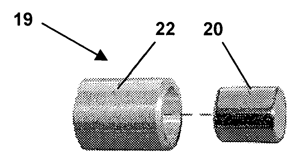
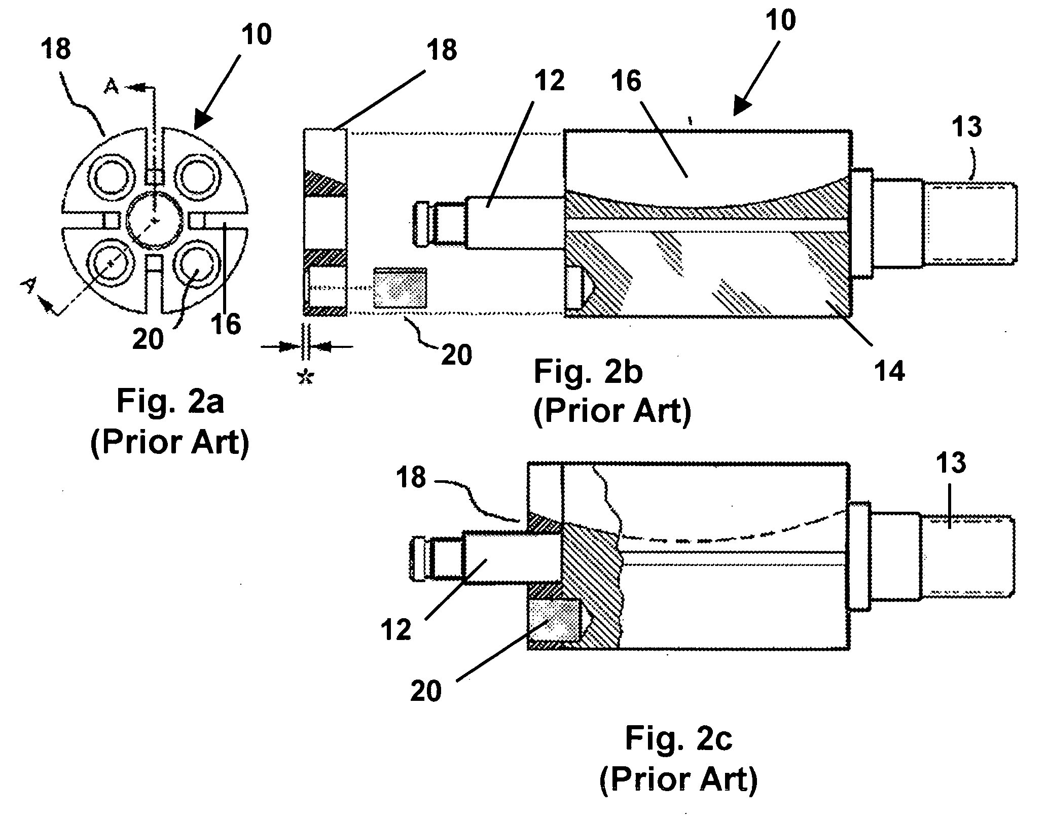
[0031]FIG. 1 is a perspective view of a rotor 10 for a conventional pneumatic tool. Rotor 10 comprises a shaft 12 upon which is affixed a rotor body 14. Shaft 12 has formed therein gear teeth 13 for enabling shaft 12 to transmit rotational for...


PUM

PropertyMeasurementUnit
nonmagneticaaaaaaaaaa
lengthaaaaaaaaaa
circumferenceaaaaaaaaaa

Abstract

A rotor for a pneumatic tool having electricity-generating capabilities comprises a shaft and an integral rotor body. For the most part, the rotor is generally of conventional design for a pneumatic tool, able to receive vanes on the rotor body and having gear teeth on the shaft. However, the rotor body further includes recesses dimensioned to received an insulated subassembly comprising a magnet received within a nonmagnetic insulator. The nonmagnetic insulator acts to allow flux to be concentrated against stator windings. The improved rotor can be used in a conventional pneumatic tool, but can also be fitted with the insulated subassemblies in order to cooperate with a stator in the tool to generate electricity upon rotation of the rotor when pressurized fluid is applied to the vanes. Thus, the differences between a conventional pneumatic tool rotor and its electricity-generating counterpart are greatly reduced compared to prior art configurations. A ring stator is connected to a supporting circuit by a connector and is supportable by a nonmagnetic end plate of the pneumatic tool. The ring stator is disposed between the rotor and the rotor bearing and is preferably formed of Silicon Core Iron “B-FM” and magnet wire.

Description

FIELD OF THE INVENTION [0001] The following is directed in general to pneumatic tools with integrated electricity generators, and more particularly to an integrated electricity generator having insulated subassemblies embedded in its rotor, and a compact stator supportable by the tool endplate. BACKGROUND OF THE INVENTION [0002] Conventional pneumatic tools, such as a pneumatic wrench, sander or grinder, typically include a motor comprised of a rotor mounted on ball bearings supported by front and rear end plates, positioned on each end of a cylinder, for rotation of the rotor within the cylinder. The rotor and cylinder are non-concentrically aligned to provide a chamber along the length of one side of the rotor for receiving pressurized fluid. The motor is further enclosed within the tool housing. The rotor is slotted lengthwise in a number of equidistant locations about its circumference to support vanes that radially slide in the slots enabling consistent contact between the vane...

Claims


Application Information

Patent Timeline
Patent Type & Authority Applications(United States)
IPC IPC(8): B23Q5/06B25F5/02F03D9/00H02K1/14H02K1/27H02K5/04H02K7/14H02K7/18H02K15/03H02K21/12
CPCB25F5/021F03D9/00F05B2220/60Y10T29/49012H02K7/183Y02E10/725F05B2220/706Y02E10/72
Inventor LEININGER, JON J.
Owner VOLT AIRE CORP
Why Eureka
Try Eureka