

Optical fiber and a method for manufacturing same
- Summary
- Abstract
- Description
- Claims
- Application Information
AI Technical Summary
Benefits of technology
Problems solved by technology
Method used
Image

Examples
first embodiment
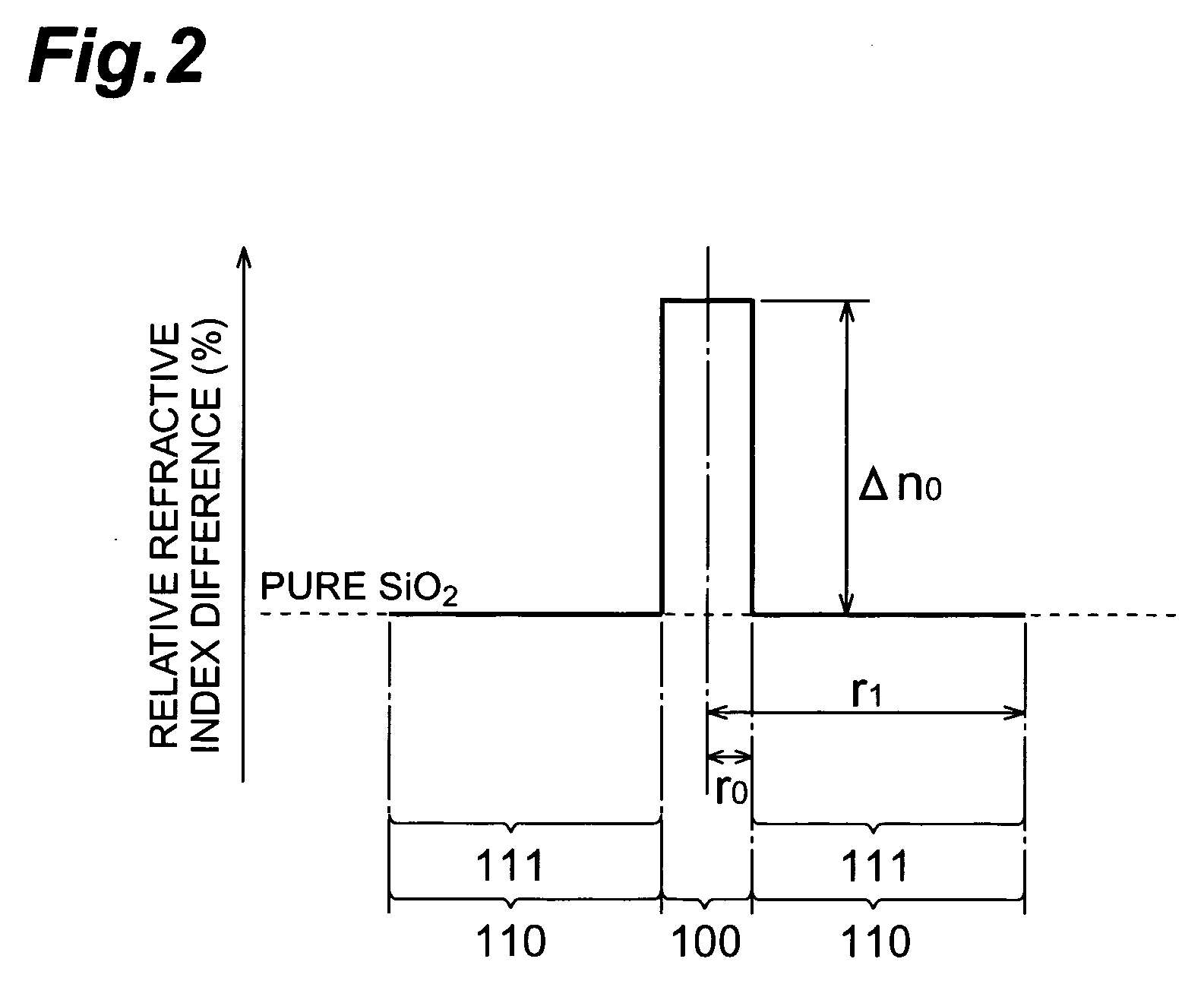
[0059]FIG. 2 is a graph showing a profile of refractive index in an optical fiber in accordance with the invention. In the graph, the abscissa axis indicates the position of each portion in the optical fiber viewed from the central axis thereof. Also, the ordinate axis indicates the relative refractive-index difference (%) with respect to the pure SiO2 at each portion in the optical fiber.
[0060] The optical fiber in accordance with this embodiment comprises a core region 100 and a cladding region 110 formed on the periphery of the core region 100. The core region 100 is formed as a layer of radius r0 including the central axis of the optical fiber. Also, the core region 100 is formed of SiO2 doped with Ge at in predetermined quantity of dopant.
[0061] To be more specific, in the core region 100, when the quantity of dopan of the Ge is represented with a relative refractive-index difference [Ge] expressed in % with respect to the pure SiO2, the Ge is added thereto in such a quantity ...
second embodiment
[0096]FIG. 5 is a graph showing a profile of refractive index in an optical fiber in accordance with the invention. In the graph, the abscissa axis indicates the position of each portion in the optical fiber on being viewed from the central axis thereof. Also, the ordinate axis indicates the relative refractive-index difference (%) with respect to the pure SiO2 at each portion in the optical fiber.
[0097] The optical fiber in accordance with this embodiment comprises a core region 200 and a cladding region 210 formed on the periphery of the core region 200. The core region 200 is formed as a layer with a radius r0 including the central axis of the optical fiber. Further, the core region 200 is formed of SiO2 doped with Ge in such a quantity of dopant that satisfies the above-described condition:
[Ge]≧0.3%.
As a consequence, the relative refractive-index difference Δn0 of the core region 200 is: Δn0=[Ge]>0.
[0098] Further, according to this embodiment, the cladding region 210 is comp...
third embodiment
[0101]FIG. 6 is a graph showing a profile of refractive index in an optical fiber in accordance with the invention. In the graph, the abscissa axis indicates the position of each portion in the optical fiber viewed from the central axis thereof. Also, the ordinate axis indicates the relative refractive-index difference (%) with respect to the pure SiO2 at each portion in the optical fiber.
[0102] The optical fiber in accordance with this embodiment comprises a core region 300 and a cladding region 310 formed on the periphery of the core region 300. The core region 300 is formed as a layer with a radius r0 including the central axis of the optical fiber. Further, the core region 300 is formed of SiO2 doped with Ge in a quantity of dopant that satisfies the above-described condition:
[Ge]≧0.3%.
Here, the relative refractive-index difference Δn0 of the core region 300 is: Δn0=[Ge]>0.
[0103] Further, according to this embodiment, the cladding region 310 is comprised of double-layered cl...
PUM
| Property | Measurement | Unit |
|---|---|---|
| Temperature | aaaaa | aaaaa |
| Temperature | aaaaa | aaaaa |
| Temperature | aaaaa | aaaaa |
Abstract
Description
Claims
Application Information