
Polarizer, polarizing plate, and liquid crystal display using the same

a technology of liquid crystal display and polarizing plate, which is applied in the direction of polarizing elements, thin material processing, instruments, etc., can solve the problems of irregular color or decoloration of the panel, and achieve the effect of reducing decoloration, preventing color change of the panel, and less dimensional chang

Inactive Publication Date: 2005-11-24
NITTO DENKO CORP
View PDF11 Cites 21 Cited by
  • Summary
  • Abstract
  • Description
  • Claims
  • Application Information

AI Technical Summary

Benefits of technology

[0008] The present invention provides a polarizer, a polarizing plate that can control or dissolve inconveniences such as color irregularity or decoloration in the display, and a liquid crystal display using the same.
[0009] Since a conventional polarizer has a large shrinkage force in the absorption axis direction, it will have a dimensional change when the polarizer or a polarizing plate using the same is exposed to heat. This leads to color irregularity or decoloration in the panel when the polarizer or the polarizing plate is packaged in a liquid crystal display. Dimensional change or warping in a panel can be corrected by decreasing residual stress applied to the entire polarizing plate. For this purpose, residual stress in a polarizer, which is generated during manufacturing (stretching) of the polarizer, is suppressed with a protective layer in order to decrease the residual stress applied to the entire polarizing plate. Specifically, shrinkage in the entire polarizing plate can be controlled by sticking a thicker protective film on the polarizer. Alternatively, film thickness of the polarizer can be reduced to decrease residual stress generated in the polarizer due to stretching and drying. In other words, shrinkage in a polarizer caused by heat stress or the like is decreased by decreasing the film thickness of the polarizer, and thus, the protective film is applied with less stress, so that shrinkage of the entire polarizing plate can be controlled. The present invention is carried out on the basis of the above estimation.
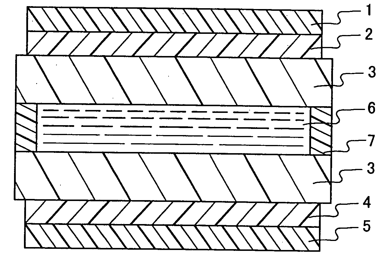
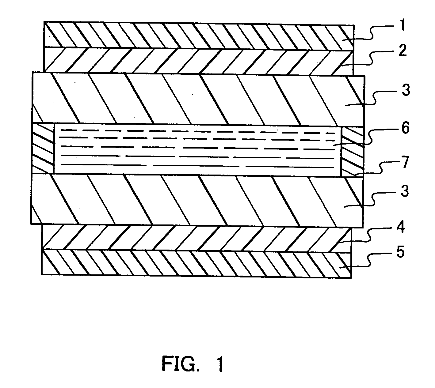
[0018] Thirdly, a liquid crystal display according to the present invention is characterized in that the polarizing plate is arranged on at least one surface of a liquid crystal cell. The liquid crystal cell comprises at least one substrate selected from a glass substrate and a plastic substrate. Since a polarizing plate of the present invention has less dimensional change, arrangement of this polarizing plate in a liquid crystal display can decrease decoloration at an end part of a display panel. Moreover, since uniform stress is applied to the liquid crystal in the cell, hue change of the panel can be prevented.

Problems solved by technology

This leads to color irregularity or decoloration in the panel when the polarizer or the polarizing plate is packaged in a liquid crystal display.

Method used


Image

  • Polarizer, polarizing plate, and liquid crystal display using the same
  • Polarizer, polarizing plate, and liquid crystal display using the same

Examples


example 1

[0063] A PVA powder having an average polymerization degree of 1700 and an average saponification degree of 97.0 mol % was dissolved in pure water and adjusted to prepare an aqueous solution of 10 wt %. The solution was applied on a polyester film and dried at 50° C. for two hours, and dried further at 130° C. for 30 minutes in order to provide a PVA film 40 μm in thickness. The film was swelled for one minute in 30° C. water, and then dripped in a 30° C. aqueous solution containing potassium iodide and iodine, and doubled in length along a predetermined axis by stretching. The ratio of the potassium iodide to the iodine in the aqueous solution was 10:1 by weight. Next, the film was further stretched in an aqueous solution comprising 4 wt % of boric acid at 50*C to have a final stretching ratio triple that of the original, and further dipped in 30° C. water to wash, dried at 50° C. for four minutes, so that a polarizer 13 μm in thickness was obtained. The concentration of iodine in ...

example 2

[0064] A PVA powder having an average polymerization degree of 1700 and an average saponification degree of 97.0 mol % was dissolved in pure water and adjusted to prepare an aqueous solution of 10 wt %. The solution was applied on a polyester film and dried at 50° C. for two hours, and dried further at 130° C. for 30 minutes in order to provide a PVA film 65 μm in thickness. The film was swelled for one minute in 30° C. water, and dipped in a 30° C. aqueous solution containing potassium iodide and iodine, and doubled in length along a predetermined axis by stretching. Ratio of the potassium iodide to the iodine in the aqueous solution was 10:1 by weight. Next, the film was stretched in an aqueous solution comprising 4 wt % of boric acid at 50° C. to have a final total stretching ratio triple that of the original, and further dipped in 30° C. water to wash, dried at 50° C. for four minutes, so that a polarizer 18 μm in thickness was obtained. The concentration of iodine in the above-...

example 3

[0065] A PVA film 40 μm in thickness obtained in Example 1 was swelled for one minute in 30° C. water, and dipped in a 30° C. aqueous solution of potassium iodide and iodine to be tripled in length along a predetermined axis by stretching. Ratio of the potassium iodide to the iodine in the aqueous solution was 10:1 by weight. Next, the film was further stretched in an aqueous solution comprising 4 wt % of boric acid at 50° C. to have a final total stretching ratio 5.5 times that of the original, and further dipped in 30° C. water to wash, dried at 50° C. for four minutes, so that a polarizer 9 μm in thickness was obtained. The concentration of iodine in the above-identified aqueous solution was 0.37 wt % so that the polarizer had a transmittance of 44%.


PUM


Abstract

The present invention provides a polarizer and a polarizing plate having less dimensional changes to heat stress. The present invention provides also a liquid crystal display that includes the polarizer and the polarizing plate, and is free of color irregularity or decoloration. The polarizer has shrinkage force of not more than 4.0 N / cm in the absorption axis direction after being heated at 80° C. for 30 minutes. A protective film is laminated on at least one surface of the polarizer in order to form a polarizing plate, and the polarizing plate has a following relationship of 0.01≦A / B≦0.16 when A denotes a thickness of the polarizer and B denotes a thickness of the protective film.

Description

[0001] The present application is a continuation of application Ser. No. 09 / 882,671 filed on Jun. 15, 2001, which is hereby incorporated by reference.BACKGROUND OF THE INVENTION [0002] 1. Field of the Invention [0003] This invention relates to a polarizing plate used for a liquid crystal display (LCD) and a liquid crystal display comprising such a polarizing plate. [0004] 2. Description of the Related Art [0005] Recently, demand for LCDs used for personal computers has increased significantly. Recently, such LCDs are used for monitoring as well. [0006] A polarizing plate used for a LCD is manufactured, for example, by a method comprising steps of: dyeing a polyvinyl alcohol (PVA) film with dichroic iodine or a dichroic dyestuff, crosslinking with an ingredient such as boric acid and borax, stretching uniaxially, and subsequently drying and sticking to a protective film (protective layer) such as triacetylcellulose (TAC). The respective steps of dyeing, crosslinking and stretching ca...

Claims


Application Information

Patent Timeline
IPC IPC(8): G02B5/30G02B7/00G02F1/1335
CPCG02B5/3033G02B7/008G02F1/133528Y10T428/24942G02F2201/54Y10T428/1041G02F2201/50C09K2323/031Y10T428/3188Y10T428/31935G02F1/133504
Inventor SUGINO, YOUICHIROUSAIKI, YUUJIKONDOU, SENRIHAMAMOTO, EIJIKUSUMOTO, SEIICHIMIHARA, HISASHITSUCHIMOTO, KAZUKI
Owner NITTO DENKO CORP
Learn More