Hydrotreating catalyst of catalytic cracking gasoline

a catalyst and cracking technology, applied in the field of hydrotreating catalysts, can solve the problems of further reducing the sulfur content of gasoline, increasing the cleaning performance of high-mileage automobiles with direct injection engines or lean burn engines, and increasing the degree of mos2 dispersion, excellent desulfurization activity, and hydrogenation suppressing

Inactive Publication Date: 2005-11-24
NAT INST OF ADVANCED IND SCI & TECH
View PDF7 Cites 39 Cited by
  • Summary
  • Abstract
  • Description
  • Claims
  • Application Information

AI Technical Summary

Benefits of technology

[0011] An object of the present invention is to provide a hydrodesulfurization catalyst for catalytic cracking gasoline having a high degree of MoS2 dispersion in the Group 8 metal of the periodic table-molybdenum-phosphorus-sulfur structure and possessing excellent desulfurization activity and hydrogenation-suppressing function against olefins and aromatics contained.

Problems solved by technology

Thus, thereafter, it is expected that high mileage automobiles having a direct-injection engine or a lean burn engine may increase.
However, since the nitrogen oxide-reducing catalyst working under oxygen-excessive conditions (lean conditions) is poisoned by sulfur content and cleaning performance lowers, it is still required to achieve further decrease of the sulfur content in gasoline.
However, the apparatus for hydrodesulfurization of these heavy oils is an apparatus requiring a high temperature and a high pressure and hence there exist many technical and economical problems in ultra-deep desulfurization of the staring oils.
However, when the catalytic cracking gasoline is hydrodesulfurized with a conventional desulfurization catalyst, there arises a problem that olefins contained in the catalytic cracking gasoline as components having a high octane number are also hydrogenated to result in decrease of the octane number.
However, there are problems that the suppression of hydrogenation of the olefins is not sufficient, the decrease of the sulfur content is limited since kinds of sulfur compounds capable of being reduced are restricted, and other facilities are necessary since a multi-step and complex process is required.
However, since hydrogenation depth of olefins is also enhanced simultaneously when the desulfurization activity against the catalytic cracking gasoline is tried to be enhanced, there arises a problem that the decrease of the octane number cannot be sufficiently suppressed.
However, since there are no attempt to quantitatively determine the degree of high dispersion of the group 6 metal sulfide and to correlate the degree with desulfurization properties of the catalytic cracking gasoline and reaction properties of olefins, there exists no sufficient guidelines for designing a catalyst for hydrotreatment of the catalytic cracking gasoline and hence it is difficult to respond requests for further improvement of the desulfurization performance and suppressing hydrogenation of olefins.

Method used


Image

  • Hydrotreating catalyst of catalytic cracking gasoline

Examples


example 1

Preparation of Catalyst:

(1) Preparation of Support

[0047] At the preparation of a catalyst, γ-alumina (shape: 1 / 16 inch cylinder) which was a porous inorganic oxide was used as a support. The surface area of the support was 195 m2 / g and the pore volume thereof was 0.80 cm3 / g.

(2) Preparation of Impregnating Solution

[0048] To a 2,000 ml beaker were added 1,500 ml of water and 64.0 g of molybdenum trioxide, followed by stirring at 95° C. for 10 hours. Then, 28.0 g of basic cobalt carbonate was added thereto, followed by stirring at 95° C. for 5 hours. The mixture was cooled to 75° C. and 130.0 g of a 50% gluconic acid solution (gluconic acid / cobalt=1.5 / l (mol / mol)) was added thereto, followed by stirring at the same temperature for 5 hours. The resulting solution was concentrated to 320 ml and subsequently 10.0 g of ammonium dihydrogen phosphate was added and dissolved to prepare an aqueous Co—Mo—P-gluconic acid solution.

(3) Preparation of Catalyst

[0049] The aqueous Co—Mo—P-gl...

example 2

Preparation of Catalyst:

(1) Preparation of Support

[0050] The same alumina support as used in Example 1 was employed.

(2) Preparation of Impregnating Solution

[0051] To a 2,000 ml beaker were added 1,500 ml of water and 64.0 g of molybdenum trioxide, followed by stirring at 95° C. for 10 hours. Then, 28.0 g of basic. cobalt carbonate was added thereto, followed by stirring at 95° C. for 5 hours. The mixture was cooled to 75° C. and 130.0 g of a 50% gluconic acid solution (gluconic acid / cobalt=1.5 / l (mol / mol)) was added thereto, followed by stirring at the same temperature for 5 hours. The resulting solution was concentrated to 424 ml and subsequently 10.0 g of ammonium dihydrogen phosphate was added and dissolved to prepare an aqueous Co—Mo—P-gluconic acid solution.

(3) Preparation of Catalyst

[0052] The aqueous Co—Mo—P-gluconic acid solution prepared in (2) was supported on the γ-alumina of (1) by an impregnation method. That is, 50 g of the γ-alumina was impregnated with 40 m...

example 3

Preparation of Catalyst:

(1) Preparation of Support

[0053] A catalyst was prepared by the same operations as in Example 1 except that the catalyst was burned. That is, to a 2,000 ml beaker were added 1,500 ml of water and 64.0 g of molybdenum trioxide, followed by stirring at 95° C. for 10 hours. Then, 28.0 g of basic cobalt carbonate was added thereto, followed by stirring at 95° C. for 5 hours. The mixture was cooled to 75° C. and 130.0 g of a 50% gluconic acid solution (gluconic acid / cobalt=1.5 / l (mol / mol)) was added thereto, followed by stirring at the same temperature for 5 hours. The resulting solution was concentrated to 320 ml and subsequently 10.0 g of ammonium dihydrogen phosphate was added and dissolved to prepare an aqueous Co—Mo—P-gluconic acid solution. With the aqueous Co—Mo—P-gluconic acid solution was impregnated 50 g of the γ-alumina. Then, the impregnated product was irradiated with a microwave having a frequency of 2.45 GHz for 10 minutes to be dried and subseq...


PUM

PropertyMeasurementUnit
temperatureaaaaaaaaaa
specific surface areaaaaaaaaaaa

Abstract

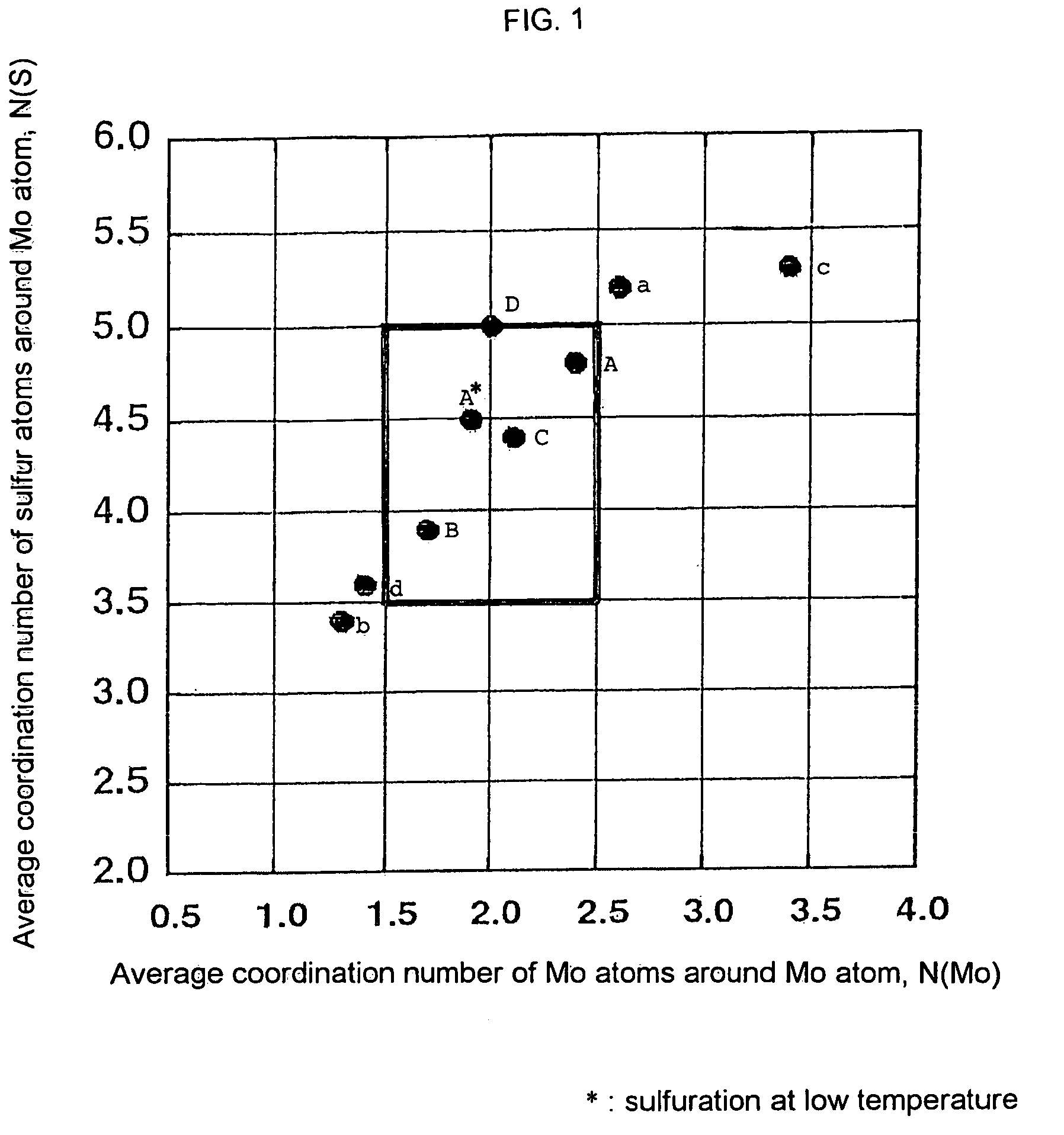
A hydrotreating catalyst comprising a Group 8 metal of the periodic table, molybdenum (Mo), phosphorus and sulfur, wherein the average coordination number [N(Mo)] of the molybdenum atoms around the molybdenum atom is from 1.5 to 2.5 and the average coordination number [N(S)] of the sulfur atoms around the molybdenum atom is from 3.5 to 5.0 when MoS2 structure in the catalyst is measured in accordance with extended X-ray absorption fine structure (EXAFS) analysis.

Description

BACKGROUND OF THE INVENTION [0001] 1. Field of the Invention [0002] The present invention relates to a hydrotreating catalyst containing molybdenum (Mo). Particularly, it relates to a hydrotreating catalyst having high desulfurization activity and desulfurization selectivity when used in hydrotreatment in which a sulfur content in catalytic cracking gasoline is reduced and also hydrogenation of olefins and aromatics is suppressed. [0003] 2. Brief Description of the Background Art [0004] Form the viewpoint of environmental protection of city and roadside air and reduction of environmental burden on a global scale, it has been required to clean exhaust gas from automobiles and reduce the discharge of carbon dioxide. With regard to gasoline-powered automobiles, in order to reduce the discharge of carbon dioxide, it is required to improve fuel economy. Thus, thereafter, it is expected that high mileage automobiles having a direct-injection engine or a lean burn engine may increase. For ...

Claims


Application Information

Patent Timeline
Patent Type & Authority Applications(United States)
IPC IPC(8): B01J27/19B01J23/88B01J23/882B01J27/188B01J35/00B01J37/02B01J37/20B01J37/28B01J37/34C10G45/04C10G45/08C10G69/04
CPCB01J23/88B01J23/882B01J35/002B01J37/0203C10G45/08B01J37/28B01J37/346C10G45/04B01J37/20Y10S502/506Y10S502/512
Inventor YOSHIMURA, YUJITOBA, MAKOTOMATSUBAYASHI, NOBUYUKIMATSUI, TAKASHI
Owner NAT INST OF ADVANCED IND SCI & TECH
Why Eureka
Try Eureka