System and methods using fiber optics in coiled tubing

a technology of fiber optics and coiled tubing, applied in the field of subterranean well operations, can solve the problems of not always being able to know what the condition of the wellbore is or what, and having no system for direct data communication between the toolstring and the surfa

Active Publication Date: 2005-12-01
SCHLUMBERGER TECH CORP
View PDF24 Cites 232 Cited by
  • Summary
  • Abstract
  • Description
  • Claims
  • Application Information

AI Technical Summary

Problems solved by technology

There is however a general lack of information at the surface as to the status of downhole coiled tubing operations.
When no clear data transfer is possible between the downhole tool and the surface, it is not always possible to know what the wellbore condition is or what state a tool is in.
Because of the flow requirements, typically there is no system for direct data communication between the toolstring and the surface.
Some devices such as running tools can be triggered by a sequence of pulling and pushing the toolstring, but again it is difficult for the surface operator to know the downhole tool status.
Direct measurement of the length of coiled tubing attached to a tool string and injected into a wellbore may not accurately represent the toolstring depth however as coiled tubing is subject to helical coiling as it is fed down the well casing.
This helical coiling effect makes estimating depth of the tool deployed on coiled tubing unpredictable.
The difficulty in gathering and conveying accurate data from deep in the subsurface to the surface often results in an incorrect representation of the downhole conditions to personnel that are making decisions in regard to the downhole operations.
Furthermore, the manner in which mud-pulse telemetry creates its signal implicitly requires a temporary obstruction in the flow; this often is undesirable in well operations.
Such an exterior deployment is operationally difficult and risks interference with wellbore completions.
The need for specialized equipment and procedures and the likelihood that the cable would wrap around the coiled tubing as it is deployed makes such a method undesirable.
Such a configuration has the advantage that the full inner diameter of the coiled tubing can be used for pumping fluids, but also has the significant disadvantage that there is no convenient way to repair such coiled tubing in the field.
It is not uncommon during coiled tubing operations for the coiled tubing to become damaged, in which case the damaged section needs to be removed from the coil and the remaining pieces welded back together.
In the presence of embedded cables or data channels, such welding operations can be complicated or simply unachievable.
Although this method provides certain functionality, it also has disadvantages.
Beyond the difficulty of installing a cable into coiled tubing, the relative size of the cable with respect to the inner diameter of the coiled tubing as well as the weight and the cost of the cable, discourage the use of cable within coiled tubing.
The relatively large exterior diameter of the cable compared to the relatively small inner diameter of the coiled tubing undesirably reduces the cross-sectional area available for fluid flow in the tube.
The weight of wireline cable provides yet another drawback to its use in coiled tubing.
Such heavy equipment is difficult to manipulate and often prevents installation of the wireline equipped coiled tubing in the field.
Moreover, the heaviness of the cable will cause it to stretch under its own weight at a rate different from the stretch of the tubular, which results in the introduction of slack in the cable.
Managing the slack, including in some cases trimming the cable or cutting back the coiled tubing string to give sufficient cable slack, can add operational time and expense to the coiled tubing operation.
There are other difficulties with using a wireline cable inside coiled tubing for data transmission.
Such known devices are failure prone and expensive.
In addition, the cable itself is subject to wear and degradation owing to the flow of fluids in the coiled tubing.
The exterior armor of the cable armor can create operational difficulties as well.
Shears optimized to cut through coiled tubing however typically are not efficient at cutting through the armored cable.

Method used


Image

  • System and methods using fiber optics in coiled tubing
  • System and methods using fiber optics in coiled tubing
  • System and methods using fiber optics in coiled tubing

Examples


Embodiment Construction

[0036] In the following detailed description and in the several figures of the drawings, like elements are identified with like reference numerals.

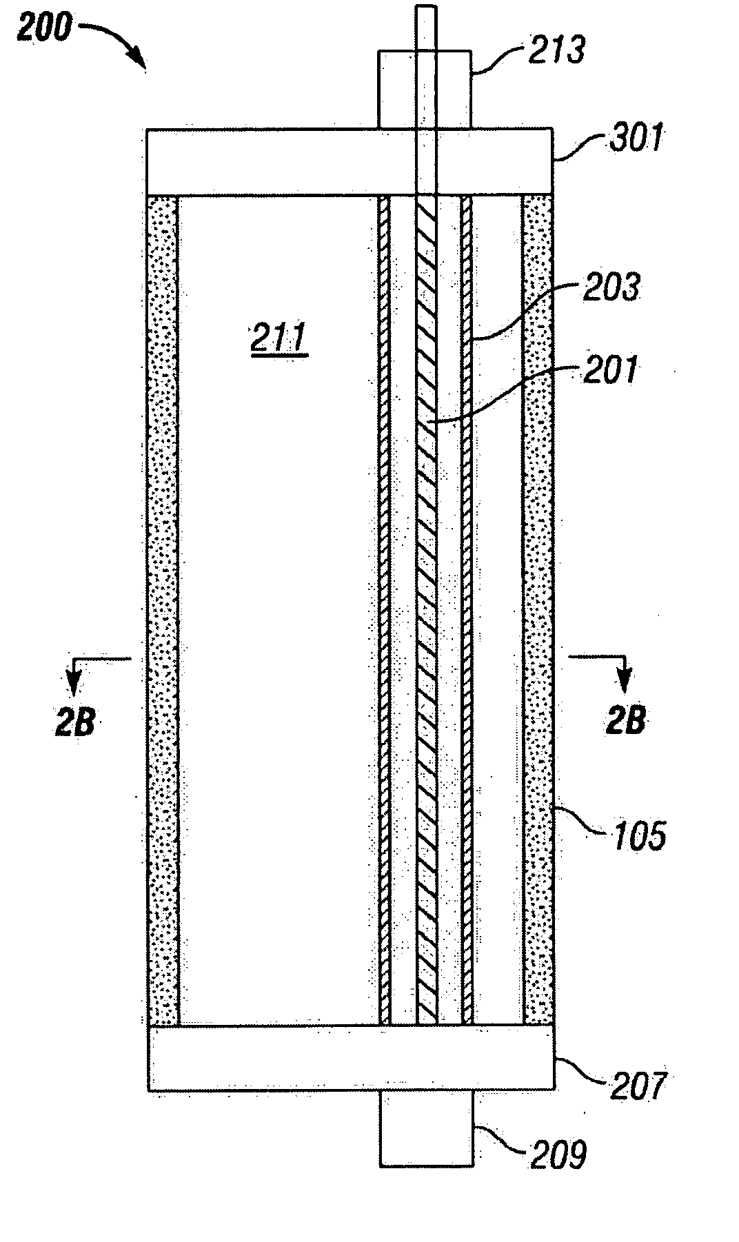
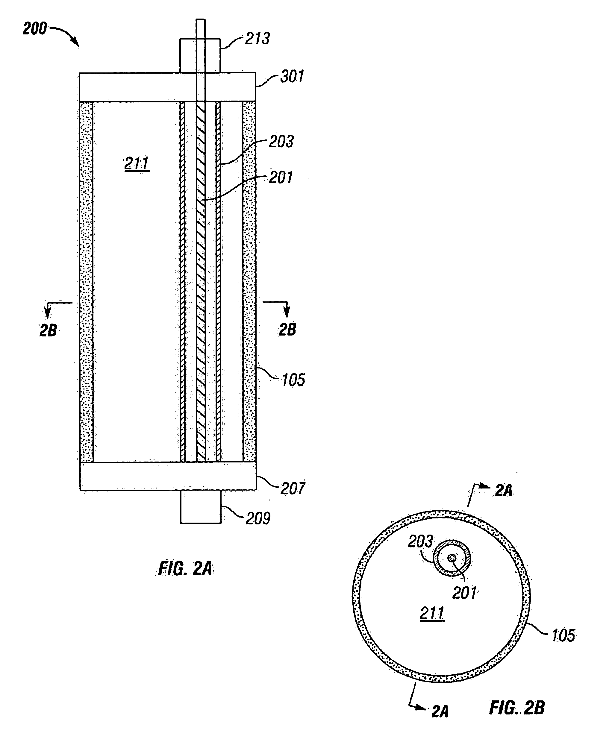
[0037] According to the present invention, operations such a well treatment operation may be performed in a wellbore using a coiled tubing having a fiber optic tether disposed therein, the fiber optic tether being capable of use for transmitting signals or information from the wellbore to the surface or from the surface to the wellbore. The capabilities of such a system provides many advantages over the performing such operations with prior art transmission methods and enables many hitherto unavailable uses of coiled tubing in wellbore operations. The use of optical fibers in the present invention provides advantages as to being lightweight, having small cross-section and provide high bandwidth capabilities.

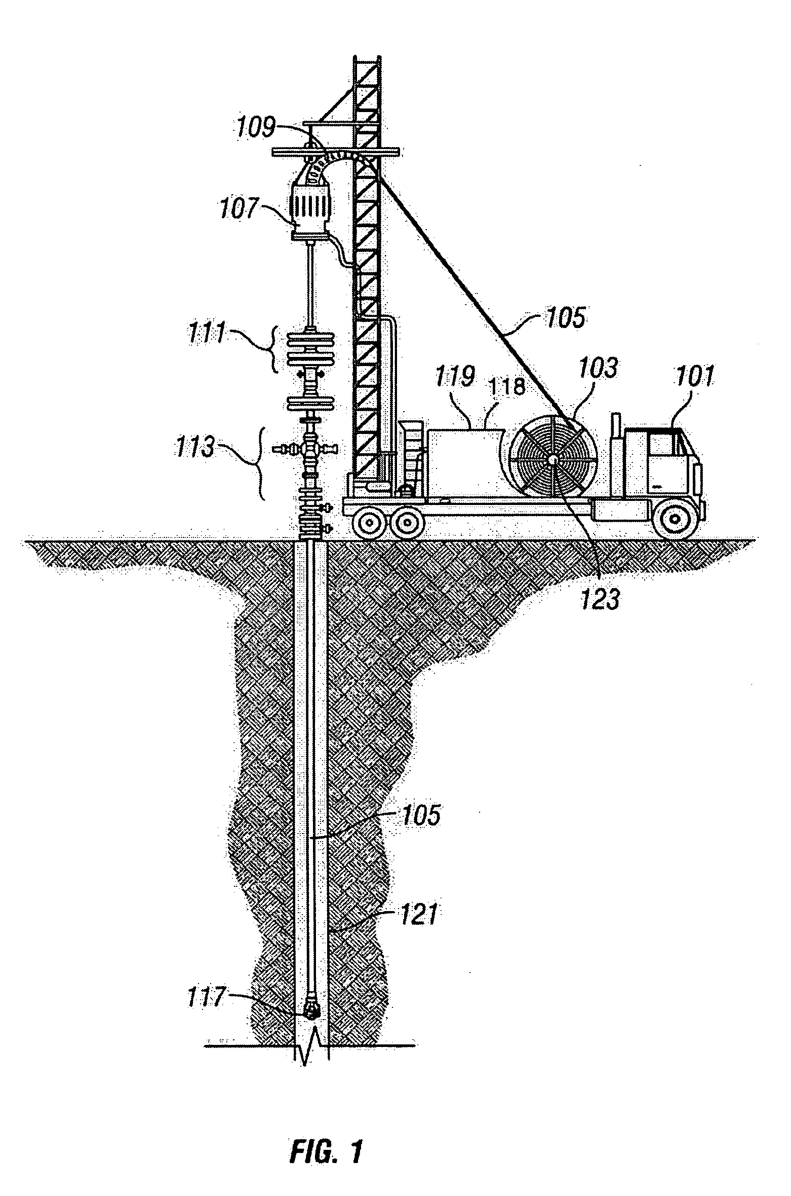
[0038] Referring to FIG. 1, there is shown a schematic illustration of equipment, and in particular surface equipment, used in a pr...


PUM


Abstract

Apparatus having a fiber optic tether disposed in coiled tubing for communicating information between downhole tools and sensors and surface equipment and methods of operating such equipment. Wellbore operations performed using the fiber optic enabled coiled tubing apparatus includes transmitting control signals from the surface equipment to the downhole equipment over the fiber optic tether, transmitting information gathered from at least one downhole sensor to the surface equipment over the fiber optic tether, or collecting information by measuring an optical property observed on the fiber optic tether. The downhole tools or sensors connected to the fiber optic tether may either include devices that manipulate or respond to optical signal directly or tools or sensors that operate according to conventional principles.

Description

[0001] This application claims priority based on U.S. provisional patent application Ser. No. 60 / 575,327 filed May 28, 2004.FIELD OF THE INVENTION [0002] The present invention relates generally to subterranean well operations, and more particularly to the use of fiber optics and fiber optic components such as tethers and sensors in coiled tubing operations. BACKGROUND OF THE INVENTION [0003] During the life of a subterranean well such as those drilled in oilfields, it is often necessary or desirable to perform services on the well to, for example, extend the life of the well, improve production, access a subterranean zone, or remedy a condition that has occurred during operations. Coiled tubing is known to be useful to perform such services. Using coiled tubing often is quicker and more economic than using jointed pipe and a rig to perform services on a well, and coiled tubing permits conveyance into non-vertical or multi-branched wellbores. [0004] While coiled tubing operations per...

Claims


Application Information

Patent Timeline
Patent Type & Authority Applications(United States)
IPC IPC(8): E21B17/20
CPCE21B47/123E21B17/206E21B23/12E21B34/06E21B34/066E21B47/135E21B2200/04E21B2200/06
Inventor LOVELL, JOHN R.GAY, MICHAEL G.ADNAN, SARMADZEMLAK, KEAN
Owner SCHLUMBERGER TECH CORP
Why Eureka
Try Eureka