Objective optical system, optical pickup apparatus and optical disk drive apparatus

Inactive Publication Date: 2005-12-01
KONICA MINOLTA OPTO
View PDF3 Cites 65 Cited by
  • Summary
  • Abstract
  • Description
  • Claims
  • Application Information

AI Technical Summary

Benefits of technology

[0020] In view of the aforementioned problems, it is an object of the present invention to provide an objective optical system, an optical pickup apparatus equipped with the objective optical system and an optical disc drive apparatus provided with the optical pickup apparatus, wherein the spherical aberration caused by the difference in the thickness of the protective layer among a high-density optical disc, DVD and CD, or spherical aberration caused by the difference in the wavelength used amon

Problems solved by technology

The aforementioned objective lens ensures a high degree of diffraction efficiency in any of the wavelength ranges, but causes the divergence of the red laser beam to be excessively intensified at the time of recording/reproducing of information using a CD.
This causes generation of excessive comatic spherical aberration at the time of tracking of the objective lens, with the result that satisfactory recording/reproducing of information using the CD cannot be ensured.
However, this prior art has the following disadvantages: The speed in recording/reproducing of information using an optical disc cannot be increased because the diffraction efficiency of the third-order diffracted light flux of the blue-violet laser beam and that of the second-order diffracted light flux are as low as 70%; the satisfactbry recording/reproducing performances cannot be ensured because of a low signal-to-noise ratio of the detection signal in the optical detector; and the laser light source is short-lived because of the high volta

Method used


Image

  • Objective optical system, optical pickup apparatus and optical disk drive apparatus
  • Objective optical system, optical pickup apparatus and optical disk drive apparatus
  • Objective optical system, optical pickup apparatus and optical disk drive apparatus

Examples


examples

[0460] The following provides a detailed description of the best form of embodying the present invention.

embodiment 1

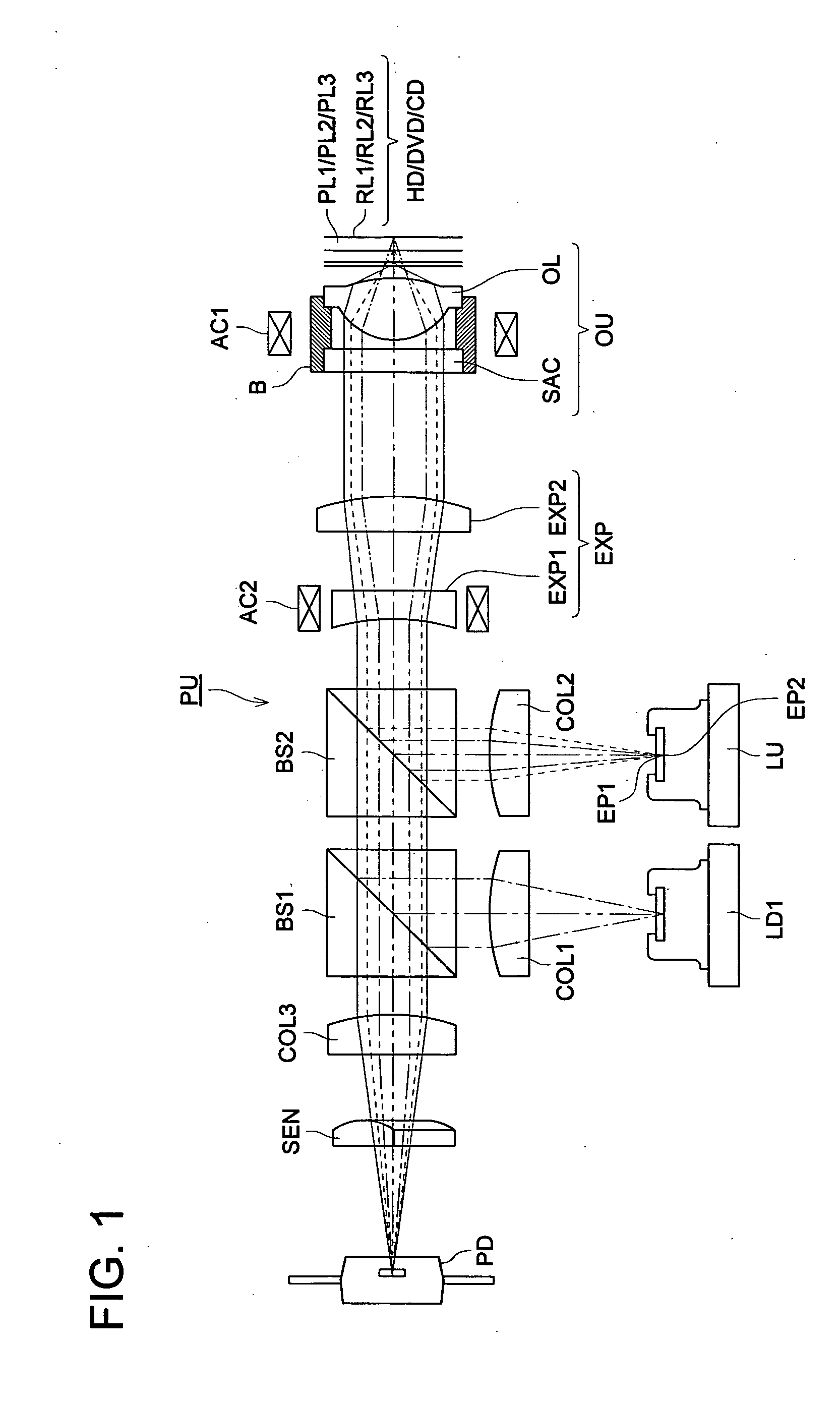
[0461] Referring to the drawings, the following describes the first embodiment of the present invention. An optical pickup apparatus PU using an objective lens unit (the objective optical system) OU as an embodiment of the present invention will be described first, with reference to FIG. 1.

[0462]FIG. 1 is a schematic view of the structure of the optical pickup apparatus PU capable of appropriate recording / reproducing of information using any of a high-density optical disc HD, DVD and CD. In terms of optical specifications, the high-density optical disc HD has the first wavelength λ1 of 405 nm, the protective layer PL1 having a thickness t1 of 0.1 mm, and the numerical aperture of NA1 of 0.85. The DVD has the second wavelength λ2 of 655 nm, the protective layer PL2 having a thickness t2 of 0.6 mm, and the numerical aperture NA2 of 0.65. The CD has the third wavelength λ3 of 785 nm, the protective layer PL3 having a thickness t3 of 1.2 mm, and the numerical aperture NA3 of 0.50. Howe...

embodiment 2

[0513] Referring to the drawing, the following describes the second embodiment of the present invention. The same structures as those of the aforementioned first embodiment will not be described to avoid duplication.

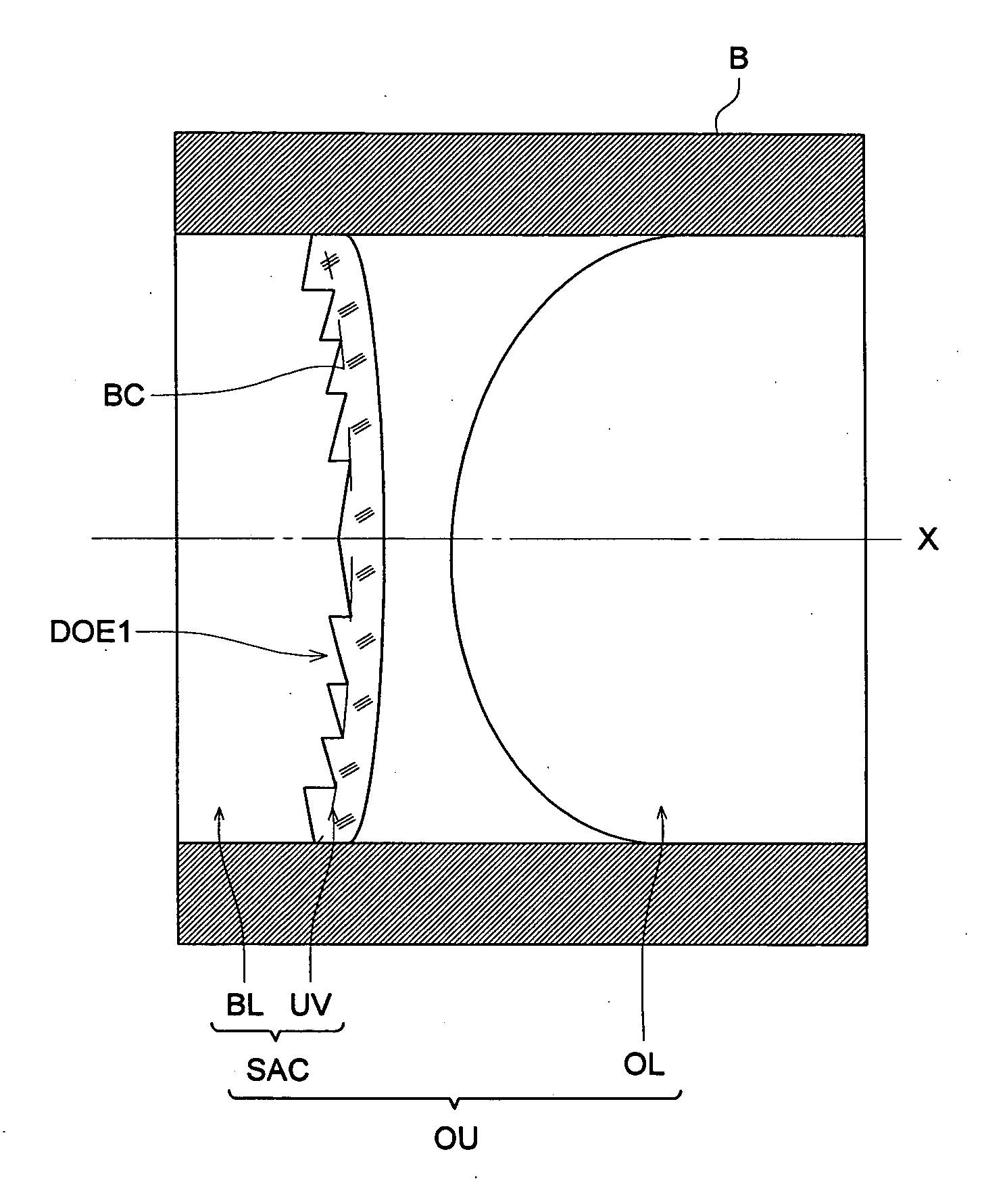
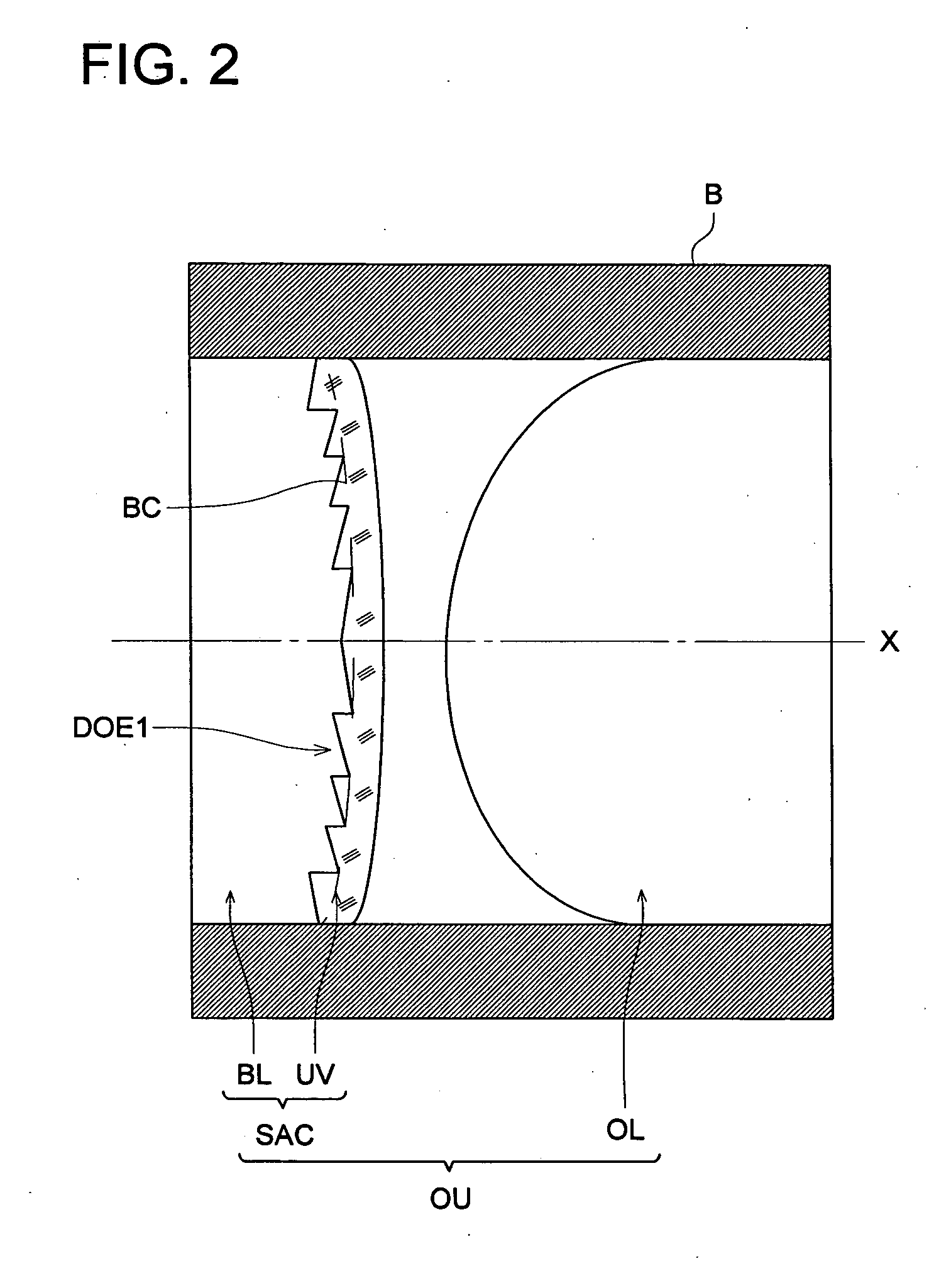
[0514] In the present embodiment, the base lens BL is made of resin, and a resin layer UV as an ultraviolet curing resin is laminated on the surface of this base lens BL.

[0515] In the present embodiment, the objective lens unit OU is characterized by addition of a phase structure different from that of the diffractive structure DOE1.

[0516] To put it more specifically, the objective lens unit OU in the present embodiment is characterized in that the aberration correcting element SAC is formed coaxially into one structure integrally with the objective lens OL whose aspherical structure is designed in such a way that spherical aberration will be minimized with respect to the first wavelength λ1 and the thickness t1 of the HD protective layer PL1, through the lens frame B...


PUM


Abstract

An objective optical system for use in an optical pickup apparatus which reproduces and/or records information on an information recording surface of first-third optical disks, the objective optical system includes a first optical element, a first part comprising a material A, a second part comprising a material b, wherein the first part and the second part are laminated on the first optical element in an optical axis of the objective optical system, and the material A and the material B have different Abbe constants for d-line each other and a first phase structure formed on a boundary between the first part and the second part.

Description

[0001] This application is based on Japanese Patent Application Nos. 2004-157798 filed on May 27, 2004, 2004-157908 filed on May 27, 2004, 2004-203417 filed on Jul. 9, 2004, 2004-230967 filed on August 6, 2004, 2004-254368 filed on Sep. 1, 2004 and 2004-267092 filed on Sep. 14, 2004 in Japanese Patent Office, the entire content of which is hereby incorporated by reference. FIELD OF THE INVENTION [0002] The present invention relates to an objective optical system, an optical pickup apparatus and an optical disc drive apparatus. BACKGROUND OF THE INVENTION [0003] What is commonly known in the prior art includes an optical pickup apparatus capable of ensuring compatibility among the high-density optical disc, DVD (based on red laser light source) and CD (based on infrared laser light source) whose recording density has been improved by the use of a blue-violet laser light source, and an optical device used for this optical pickup apparatus (e.g. Patent Documents 1, 2 and 3). [0004] [Pa...

Claims


Application Information

Patent Timeline
IPC IPC(8): G11B7/00G11B7/135
CPCG11B7/1353G11B7/13922G11B7/1374
Inventor KIMURA, TOHRUMORI, NOBUYOSHIATARASHI, YUICHIIKENAKA, KIYONO
Owner KONICA MINOLTA OPTO
Why Eureka
Try Eureka