
Dual laser coating apparatus and process

Active Publication Date: 2005-12-01
PHOTOFUSION TECH
View PDF7 Cites 21 Cited by
  • Summary
  • Abstract
  • Description
  • Claims
  • Application Information

AI Technical Summary

Benefits of technology

[0014] Temperature control is enhanced by the ability to superheterodyne two lasers at separate frequencies. This allows for better absorption of certain materials being fused by the laser. Another common problem associated with laser processing occurs as the polymer heats up. During the heating process the spectral lines are Doppler broadened and slightly shifted. This can affect the absorption of a laser of a fixed wavelength. With the present invention, the optimum laser frequency can be turned to a more optimum frequency for absorption still with sufficient power for fast efficient thermal processing.
[0015] As thicker coatings are applied, especially those above 90 mil inches or 2 mm thick, the coating begins to break down under conditions of thermal stress as experienced in conventional oven systems. In the present invention, these conditions are avoided since the dual laser system fuses these polymers in an absolute minimum time. Therefore, the slow degradation and dissolution of polymers in oven techniques are avoided. Further, the melt flow times with the dual laser system are dramatically reduced compared to a single laser system.
[0016] The system utilizes fluoropolymers and other chemical resistant coatings applied to objects such as chemical processing equipment and the like. Further, this invention applies coatings of high melt or processing temperatures over sensitive substrates such as fiberglass, etc. These coatings protect structures and apparatus from virtually any environmental or man-made hazards.

Problems solved by technology

Another common problem associated with laser processing occurs as the polymer heats up.

Method used


Image

  • Dual laser coating apparatus and process
  • Dual laser coating apparatus and process
  • Dual laser coating apparatus and process

Examples


Embodiment Construction

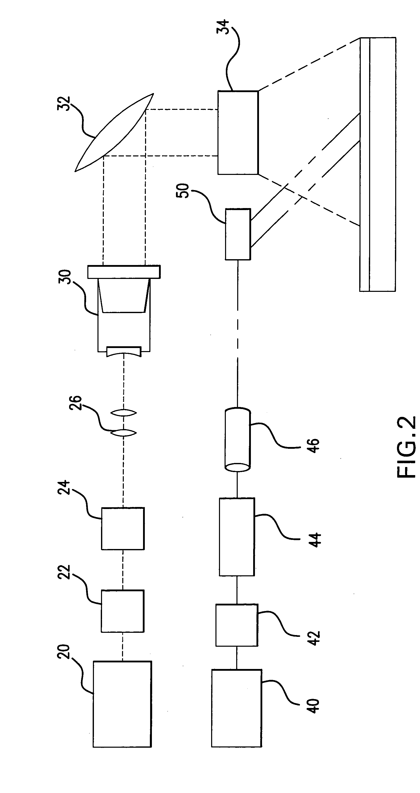
[0021] Powdered coatings have a lower melt and upper melt temperatures. At the lower melt temperature, the powder begins to liquify and flow. At the upper melt temperature, the polymer structure of the coating begins to break down and are rendered useless. The difference between the upper and lower melt temperatures may be small and the difference between the optimum melt flow temperature and polymer dissolution temperature may be as little as two degrees. In the coating process, two lasers may be used. The first laser heats the substrate and coating to the lower melt point and a second, smaller laser having a more absorptive frequency further heats the coating.

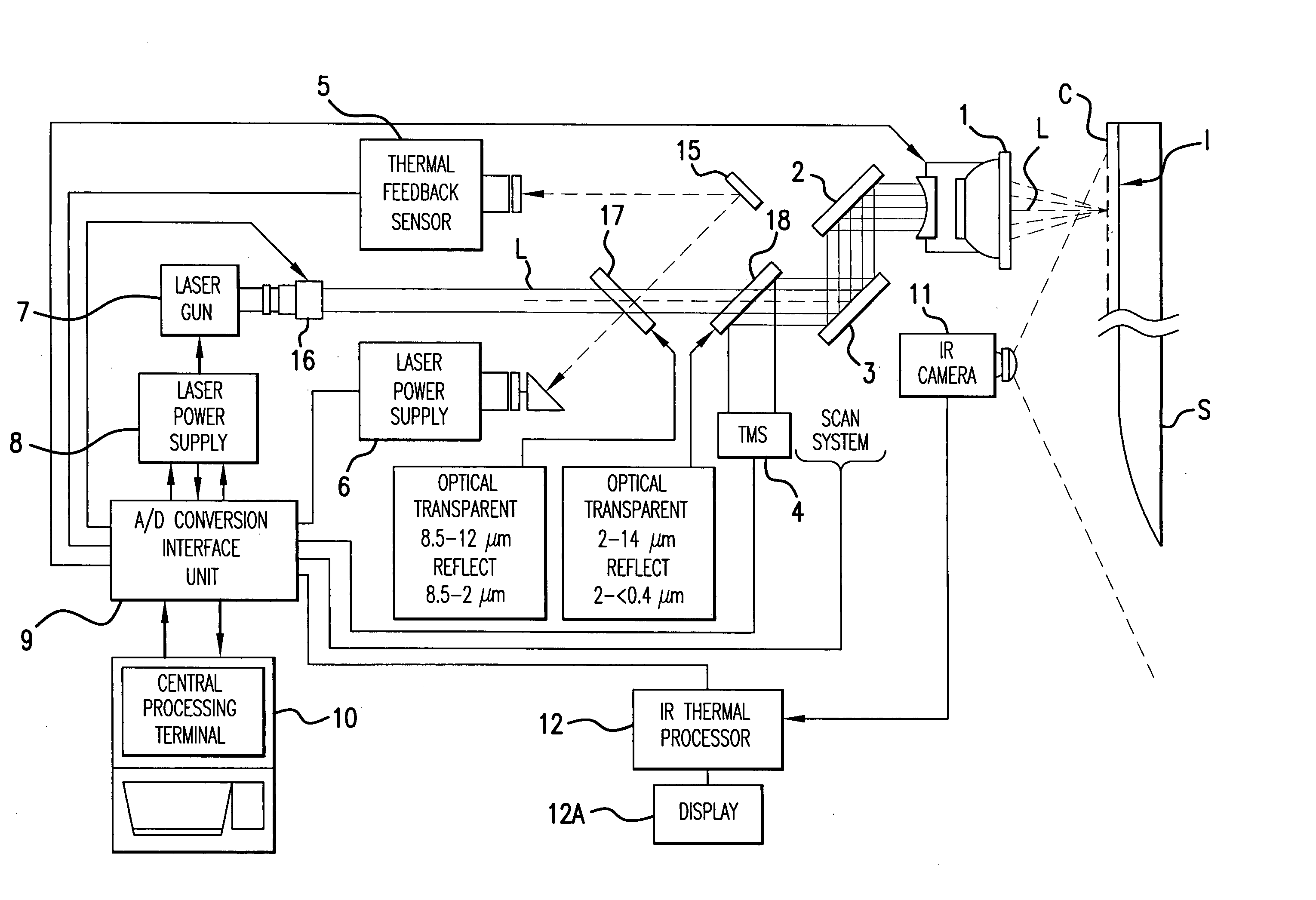
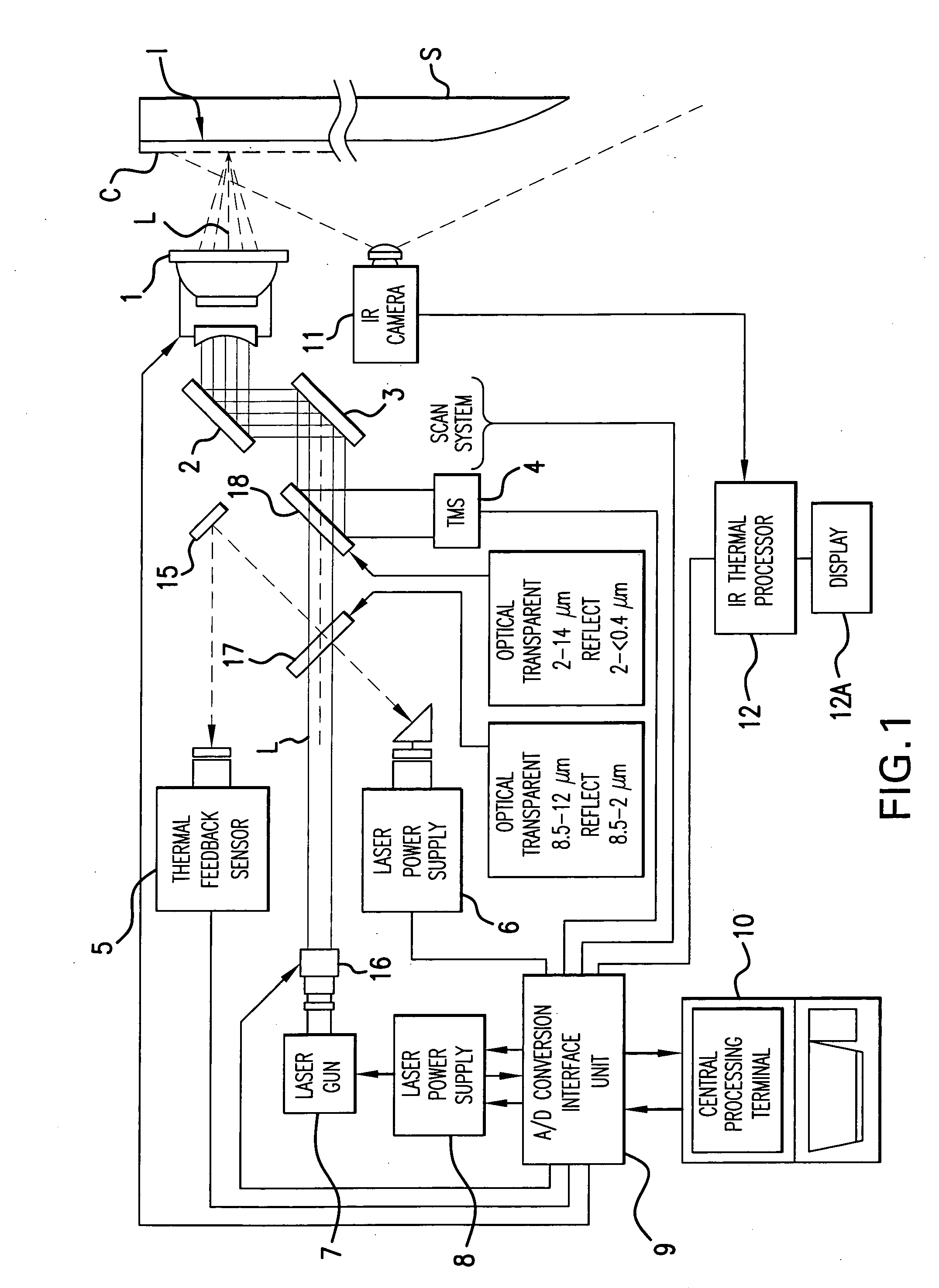
[0022] In FIG. 1, a computer 10 controls the process, including the laser power supply 8 to the laser gun 7. A laser beam L emits from the laser head 16 and passes through two dichroic 17,18 before passing galvos 2, 3 and entering head unit 1 after which the laser L is directed at substrate S to melt the coating C. An IR cam...


PUM

PropertyMeasurementUnit
Temperatureaaaaaaaaaa
Heataaaaaaaaaa

Abstract

An apparatus for applying and fusing a powder coating to substrates of various composition uses two lasers to accurately heat the coating to the optimum temperature. A second laser has less power and heats a smaller area than the first laser. Temperature control is enhanced by the ability to superheterodyne two lasers at separate frequencies. This allows for better absorption of certain materials being fused by the laser. Another common problem associated with laser processing occurs as the polymer heats up. During the heating process the spectral lines are Doppler broadened and slightly shifted. This can affect the absorption of a laser of a fixed wavelength. With the present invention, the optimum laser frequency can be turned to a more optimum frequency for absorption still with sufficient power for fast efficient thermal processing.

Description

[0001] This application claims the benefit of provisional application Ser. No. 60 / 539,980, filed Jan. 30, 2004.BACKGROUND OF THE INVENTION [0002] Field of Use [0003] This invention relates to the field of use of fluorocarbon coatings applied to various substrates. It particularly pertains to sensitive substrates such as composites and the like. In particular, it relates to a method by which two lasers are utilized together to offer advantages over prior art. [0004] Powder coatings are common to the industry and are typically cured or fused using oven systems. One ubiquitous example is polytetrafluoroethylene (PTFE) coatings on cookware. Other coatings include nylon-12, polyethylene and polyurethane. The coating material is applied to the substrate as a powder and must be heated to a viscous fluid in order to bond to the substrate. The oven systems used to bond the powders to substrates are large, expensive and inefficient. There is no possibility to fine tune the process to optimize...

Claims


Application Information

Patent Timeline
IPC IPC(8): A47J27/00B05C5/00B05D3/02B05D3/06B05D5/08B29C71/02
CPCA47J27/002A47J36/025B05D3/0209B05D2401/32B05D3/06B05D5/083B05D3/0254
Inventor POULLOS, MARK PETER
Owner PHOTOFUSION TECH
Learn More