Fuel cell stack

a fuel cell and stack technology, applied in the field of fuel cell stacks, can solve the problems of degrading the power generation performance of the overall fuel cell stack, metal contamination of coolant, electron leakage to the coolant passage or the radiator, etc., and achieves the effect of maintaining the power generation performance and simple and compact structur

Inactive Publication Date: 2005-12-01
HONDA MOTOR CO LTD
View PDF5 Cites 27 Cited by
  • Summary
  • Abstract
  • Description
  • Claims
  • Application Information

AI Technical Summary

Benefits of technology

[0015] A main object of the present invention is to provide a fuel cell stack having a simple and compact structure in which the temperature of surfaces of the power generation cells does

Problems solved by technology

Even if deionized water or pure water is used as the coolant, the coolant may be contaminated by metals, for example, and become conductive in circulating a coolant passage or a radiator during the operation of the cooling system.
While electrons produced by the electrochemical reactions in the power generation cells are collected from terminal plates at opposite ends of the fuel ce

Method used


Image

  • Fuel cell stack
  • Fuel cell stack
  • Fuel cell stack

Examples


first embodiment

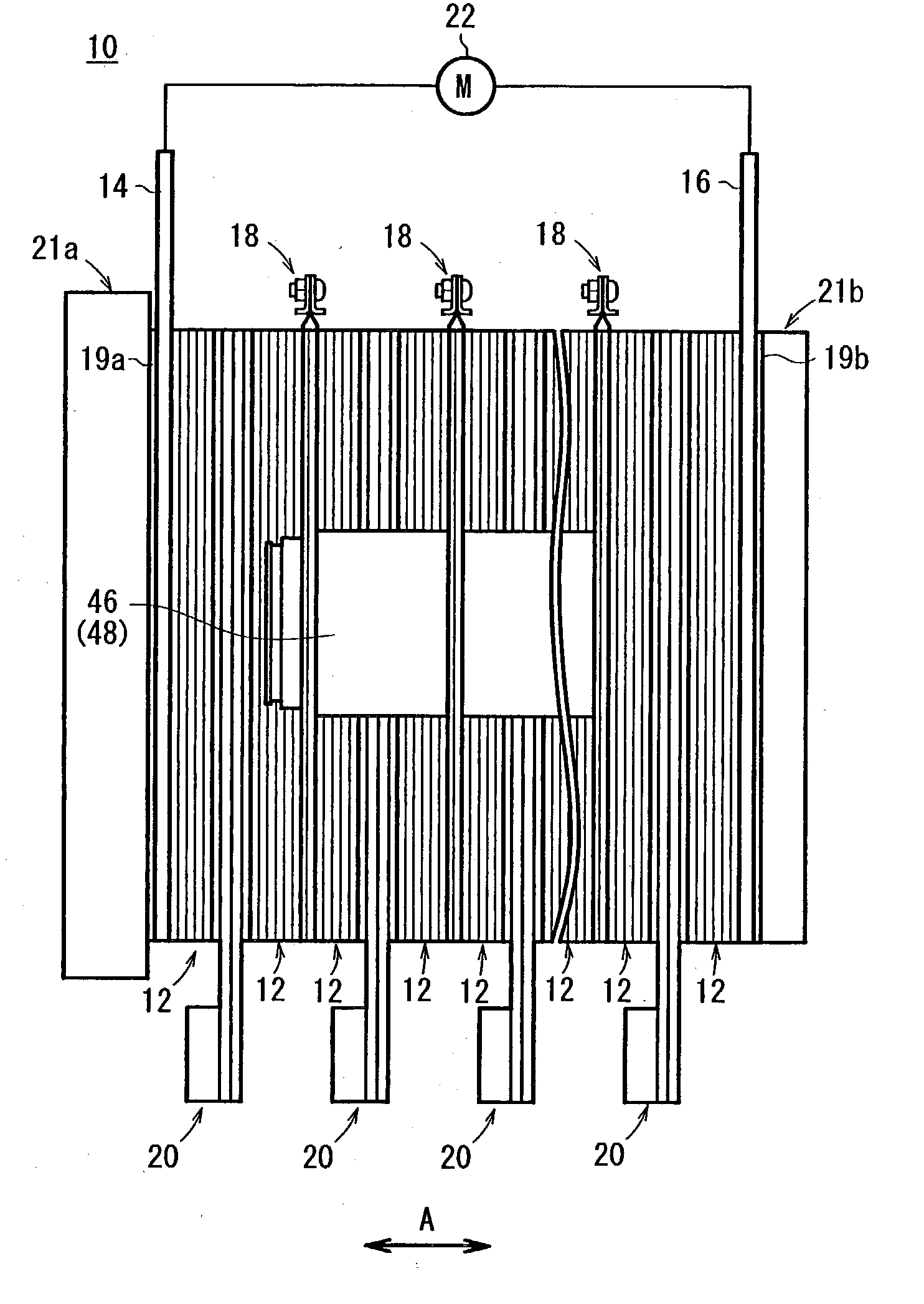
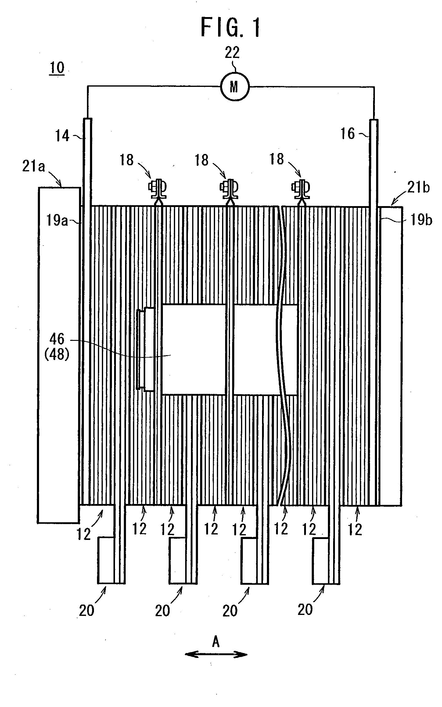
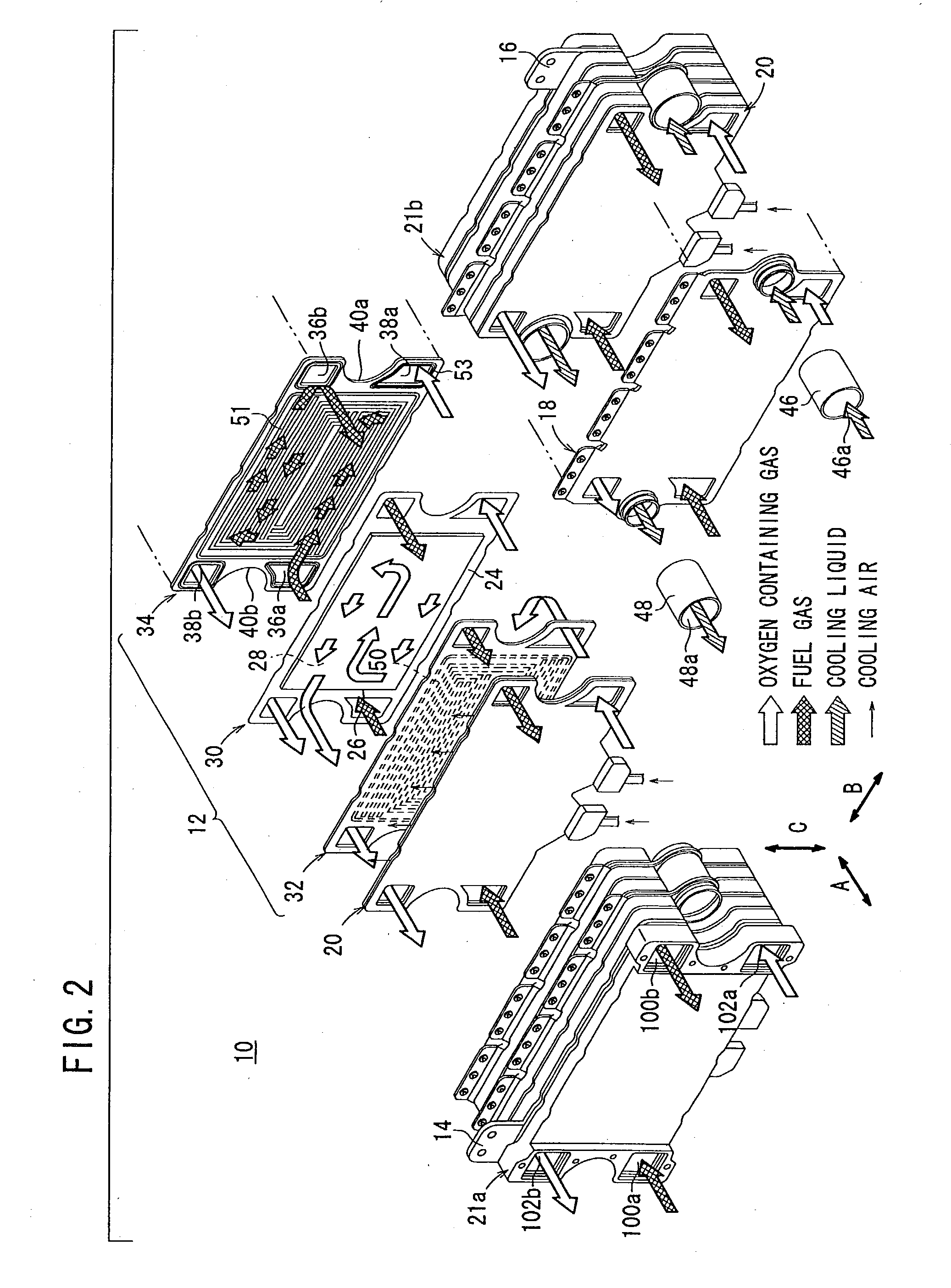
[0040]FIG. 1 is a side view schematically showing a fuel cell stack 10 according to the present invention. FIG. 2 is an exploded perspective view showing the fuel cell stack 10. FIG. 3 is an enlarged view showing main components of the fuel cell stack 10.

[0041] The fuel cell stack 10 is formed by stacking a predetermined number of power generation cells 12 in a stacking direction indicated by an arrow A.

[0042] Terminal plates 14, 16 are provided on the outside of outermost power generation cells 12 in the stacking direction. The terminal plates 14, 16 are connected to the power generation cells 12 electrically. A predetermined number of first cooling cells 18 and second cooling cells 20 are interposed between the terminal plates 14, 16. The first cooling cells 18 and the second cooling cells 20 are arranged alternately. A predetermined number of the power generation cells 12 are interposed between the first cooling cell 18 and the second cooling cell 20.

[0043] Insulator sheets 19a...

second embodiment

[0103] In the second embodiment, each of second cooling cells 20 is interposed between adjacent first cooling cells 18. Specifically, as shown in FIGS. 9 and 10, the second cooling cell 20 is not interposed between the terminal plate 14 of the fuel cell stack 160 and an outermost first cooling cell 18, and between the terminal plate 16 of the fuel cell stack 160 and the other outermost first cooling cell 18. The second cooling cells 20 are disposed only centrally between the adjacent first cooling cells 18. Ten power generation cells 12 are interposed between the adjacent first cooling cells 18, and the second cooling cell 20 is interposed between the adjacent first cooling cells 18 at intervals of five power generation cells 12. Five power generation cells 12 are interposed between the terminal plate 14 and the first cooling cell 18 adjacent to the terminal plate 14. Likewise, five power generation cells 12 are interposed between the terminal plate 16 and the first cooling cell 18 ...

third embodiment

[0106]FIG. 11 is a side view schematically showing a fuel cell stack 170 according to the present invention.

[0107] In the fuel cells stack 170, third cooling cells 172 are provided outside the terminal plates 14, 16 oppositely to power generation cells 12. Specifically, insulator sheets 19a, 19b are provided on the terminal plates 14, 16, and the third cooling cells 172 are disposed on the insulator sheets 19a, 19b. Thermal insulators 174 are disposed on the third cooling cells 172, and end plates 21a, 21b are disposed on the thermal insulators 174.

[0108] The third cooling cells 172 are insulated from the terminal plates 14, 16 by the insulator sheets 19a, 19b. Since the third cooling cells 172 do not connect the power generation cells 12 electrically, no conductive plates are needed for the third cooling cells 172. As shown in FIG. 12, the third cooling cell 172 has a passage plate 52 and a cover plate 56.

[0109] In the third embodiment, the third cooling cells 172 are provided ou...


PUM


Abstract

A fuel cell stack includes power generation cells, terminal plates, first cooling cells, and second cooling cells. The terminal plates are electrically connected to the power generation cells. The first cooling cells are interposed between the terminal plates, and a cooling liquid is supplied to the first cooling cells for cooling the power generation cells. The second cooling cells are interposed between the terminal plates. A predetermined number of power generation cells are interposed between the first cooling cell and the second cooling cell. A cooling air is supplied to the second cooling cell for cooing the power generation cells.

Description

BACKGROUND OF THE INVENTION [0001] 1. Field of the Invention [0002] The present invention relates to a fuel cell stack of power generation cells formed by stacking a plurality of electrolyte electrode assemblies and separators alternately. Each of the electrolyte electrode assemblies includes an anode, a cathode, and an electrolyte interposed between the anode and the cathode. A fuel gas is supplied to the anode, and an oxygen-containing gas is supplied to the cathode for generating electricity in the power generation cells. [0003] 2. Description of the Related Art [0004] For example, a phosphoric acid fuel cell (PAFC) is a power generation cell which employs a porous electrolyte layer of silicon carbide matrix for retaining concentrated phosphoric acid. The electrolyte layer is interposed between carbon-based electrodes (anode and cathode) to form an electrolyte electrode assembly. The electrolyte electrode assembly is interposed between separators (bipolar plates). The electrolyte...

Claims


Application Information

Patent Timeline
IPC IPC(8): H01M8/00H01M8/02H01M8/04H01M8/10H01M8/24
CPCH01M8/04007H01M8/04014H01M8/04029Y02T90/32H01M8/241H01M2250/20Y02E60/50H01M8/04074Y02T90/40H01M8/2483H01M8/0267H01M8/2457H01M8/0263H01M8/0271
Inventor SATO, SHUJIISE, MASAHIROOKAZAKI, KOJI
Owner HONDA MOTOR CO LTD
Why Eureka
Try Eureka