Wellbore evaluation system and method

a wellbore and evaluation system technology, applied in the field of equipment and techniques to evaluate wellbore conditions, can solve the problems of fatigue cracking, thin operating margin, failure of both sucker rods and the production tubing in which they move,

Active Publication Date: 2005-12-01
ROBBINS & MYERS ENERGY SYST
View PDF10 Cites 53 Cited by
  • Summary
  • Abstract
  • Description
  • Claims
  • Application Information

AI Technical Summary

Benefits of technology

[0016] A wellbore evaluation system and method are provided for evaluating one or more of wear and corrosion to certain critical components of a well system. The well system includes a production tubing string positionable in a well and a sucker rod string movable within the production tubing string. In one embodiment, two or more sensors are selected from the group consisting of a deviation sensor movable within the well to determine a deviation profile; a rod sensor for sensing and measuring wear, corrosion pitting, cross-sectional area and diameter of the sucker rod string as it is removed from the well to determine a rod profile; and a tubing sensor for sensing and measuring wear, cross-sectional area, corrosion pitting, and / or holes or splits in the production tubing string as it is removed from the well to determine a tubing profile. A computer system, which may broadly include a central server-computer, a data acquisition computer system, and circuitry connected to the individual two or more sensors, is in communication with the two or more sensors for computing and comparing two or more of the respective deviation profile, rod profile, and tubing profile as a function of depth in the well. The computer preferably compares all three of the deviation profile, rod profile, and tubing profile.

Problems solved by technology

This is often the case with mature producing fields where production has declined and operating margins are thin.
A number of factors conspire to wear down and eventually cause failure in both sucker rods and the production tubing in which they move.
Produced fluid is often corrosive, attacking the sucker rod surface and causing pitting that may lead to loss of cross-sectional area or fatigue cracking and subsequent rod failure.
Produced fluid can also act like an abrasive slurry that can lead to mechanical failure of the rod and tubing.
The rod and tubing also wear against each other.
Even boreholes believed to have been drilled so as to be truly vertical and considered to be nominally straight may deviate considerably from true vertical, due to factors such as drill bit rotational speed, weight on the drill bit, inherent imperfections in the size, shape, and assembly of drill string components and naturally-occurring changes in the formation of the earth that affect drilling penetration rate and direction.
As a result, sucker rods and production tubing are never truly concentric, especially during the dynamics of pumping, and instead contact one another and wear unpredictably over several thousand feet of depth.
Additionally, in certain conditions, such as in geologically active areas or in areas of hydrocarbon production from diatomite formations, wellbores may shift over time, causing additional deviation from vertical.
However, in the case of most existing rod-pumped oil wells, any such surveys performed during the original drilling of the well largely comprised periodic surveys of wellbore direction and inclination performed only at one or two key intervals during the well-drilling operation.
Consequently, a continuous profile of the wellbore deviation, giving rise to tubing and rod wear, is not generally known.
Alternatively, performing a dedicated, continuous directional survey of existing wellbores, such as those contemplated in the above patents, is generally cost-prohibitive.
Failure of pumped oil wells due to the cumulative effect of the wear of sucker rods on tubing and such wear combined with corrosion is considered to be the single largest cause of well down time.
Since many of these mitigation techniques are expensive to apply, oil well operators must carefully assess the economics of any such mitigation techniques.
Although wear can be mitigated, it cannot be eliminated, so inspection of sucker rods and production tubing are common in the industry.
Well operators within the industry commonly follow a “run until failure” approach, only inspecting components upon failure of some element of the wellbore, which may include a hole or split in the tubing, pump failure, rod failure, or tubing separation.
The nature of the industry is that down-time is costly, both in terms of lost or deferred production and the actual cost to repair the failure by work-over of the wellbore.
Another reason well operators are reluctant to perform inspections at regular intervals is that the diagnostic capabilities of current inspection practices are somewhat limited.
Further, many operators are unable to devote the time and human resources to perform the necessary analysis of data such as well deviation, rod failure and tubing failure.
Caliper surveys are available to measure the inside diameter of production tubing but cannot examine the condition of the outside condition of the tubing.
Surface defects result in magnetic flux leakage.
Ironically, however, the analyses derived from the resulting data are relatively limited and shortsighted.
The data obtained is not optimally used to correct or mitigate wear.
Additionally, because the production tubing in most rod-pumped producing wells is tubing that has previously been used in other wells or from such reclaimed supplies, pre-existing wear patterns on tubing alone are often misleading as to the root causes of tubing wear in the current wellbore.
Further, even a detailed, positional analysis of defects does not provide an adequate window as to their root cause or mitigation.
This technique, however, reduces the inside diameter of the tubing and does not assess the cause of tubing wear.
As a result, the polythene liner may simply fail over time, rather than the tubing, which still necessitates work-over.
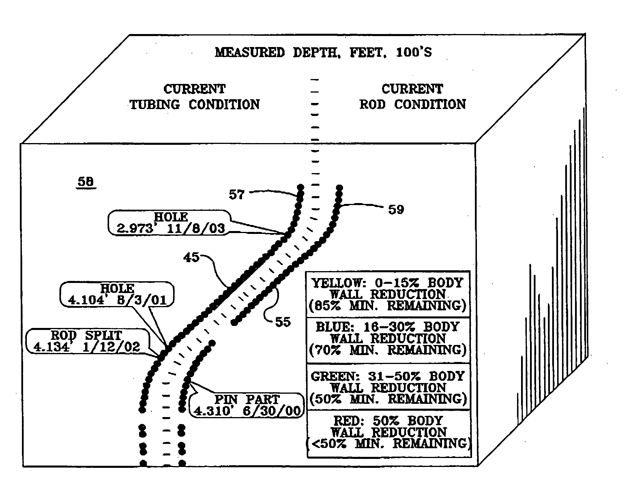
Not even “real time” data reports provide an adequate solution to mitigating wear, because they do nothing to improve the quality or scope of the analysis, or correlate tubing condition information with rod condition information.
Another problem with existing inspection systems is that there is no available means of performing these assessments in a cost-effective and timely manner so that tubing wear can be mitigated through an economical solution specific to a well.
Because quickly returning the well to production is of paramount importance, full analysis of any limited information available is often difficult, if not impossible, to perform before the well is returned to production.

Method used


Image

  • Wellbore evaluation system and method
  • Wellbore evaluation system and method
  • Wellbore evaluation system and method

Examples


Embodiment Construction

[0034] A preferred embodiment of a wear evaluation system is indicated generally at 10 in FIG. 1. An embodiment of sensor package 12 including a rod sensor and tubing sensor is detailed further in FIG. 2. The sensor package 12 may be positioned on a rig floor. A deviation sensor 28 is detailed further in FIG. 3, as it is dropped to the bottom of well 7 in the production tubing string 20 by gravity or lowered on wireline 32 through tubing string 20. The system 10 evaluates wear, corrosion pitting, cross-sectional area and certain diameters of components of a well system that includes a segmented production tubing string 20 positionable in well 7 and a segmented sucker rod string 18 movable within the production tubing string 20. Segmented sucker rod string 18 has multiple segments coupled together with larger diameter couplings 19, although a sucker rod string may alternatively be a continuous rod or “COROD”. Sucker rod strings may include both reciprocating type rods, which reciproc...


PUM


Abstract

A wellbore evaluation system evaluates mechanical wear and corrosion to components of a well system including a production tubing string positionable in a well and a sucker rod string movable within the production tubing string. A deviation sensor determines a deviation profile of the well, a rod sensor senses and measures wear and corrosion to the sucker rod string as it is removed from the well to determine a rod profile, and a tubing sensor senses and measures wear and corrosion to the production tubing string as it is removed from the well to determine a tubing profile. A data acquisition computer is in communication with the sensors for computing and comparing two or more of the respective deviation profile, rod profile, and tubing profile as a function of depth in the well. A 3-dimensional image of wellbores, with isogram mapping, may be generated and examined over the internet.

Description

FIELD OF THE INVENTION [0001] The present invention relates to equipment and techniques to evaluate wellbore conditions. More particularly, the invention relates to improved techniques to evaluate wear and corrosion in a wellbore having a downhole pump driven by a sucker rod powered at the surface. BACKGROUND OF THE INVENTION [0002] Oil and gas wells are typically drilled with a rotary drill bit, and the resulting borehole is cased with steel casing cemented in the borehole to support pressure from the surrounding formation. Hydrocarbons may then be produced through smaller diameter production tubing suspended within the casing. Although fluids can be produced from the well using internal pressure within a producing zone, pumping systems are commonly used to lift fluid from the producing zone in the well to the surface of the earth. This is often the case with mature producing fields where production has declined and operating margins are thin. [0003] The most common pumping system ...

Claims


Application Information

Patent Timeline
Patent Type & Authority Applications(United States)
IPC IPC(8): E21B47/02E21B43/12E21B47/002E21B47/08
CPCE21B43/127E21B47/0007E21B47/082E21B47/022E21B47/0008E21B47/008E21B47/009E21B47/085
Inventor WARD, SIMON J.
Owner ROBBINS & MYERS ENERGY SYST
Why Eureka
Try Eureka