Vaccum film-forming apparatus

a vacuum film and film-forming technology, applied in vacuum evaporation coatings, transportation and packaging, coatings, etc., can solve the problems of difficulty in filling holes and/or trenches with conductive films in good or high coverage, defects and troubles, and foregoing conventional techniques never permit separate and independent setting of such process conditions. , to achieve the effect of excellent film quality and low cos

Active Publication Date: 2005-12-08
ULVAC INC
View PDF5 Cites 42 Cited by
  • Summary
  • Abstract
  • Description
  • Claims
  • Application Information

AI Technical Summary

Benefits of technology

[0035] As has been described above in detail, the vacuum film-forming apparatus according to the present invention permits the independent establishment of the process conditions for adsorption and reaction steps, the acceleration of the reaction between a raw gas and a reactant gas and the formation of a thin film having more excellent film quality. Moreover, the apparatus likewise permits the considerable reduction of the cycle time of film-forming processes and the apparatus can be manufactu...

Problems solved by technology

If the aspect ratio increases in this manner, it would be difficult to fill up such holes and/or trenches with a conductive film in a good or high coverage.
When using, for instance, Cu as a principal distributing wire material in the case of the foregoing embedded distributing wire structure, deposited Cu may easily diffuse into the neighboring insulating film and this becomes a cause of various defects and troubles.
However, the foregoing conventional technique never permits the separate and independent setting of such process conditions, but simply the raw and reactant gases can separately and periodically be fed to the substrate and accordingly, i.e. there is a time lag between a raw gas introduction and a reactant gas introduction, and a thin film is formed by repeatedly depositing a layer having a thickness of several atoms.
Accordingly, this suffers from such problems that it takes a long period of time for the transfer of the substrate and that this in turn makes, impossible, the reduction of the cycle time for the formation of desired thin films.
Furthermore, i...

Method used


Image

  • Vaccum film-forming apparatus
  • Vaccum film-forming apparatus
  • Vaccum film-forming apparatus

Examples


Embodiment Construction

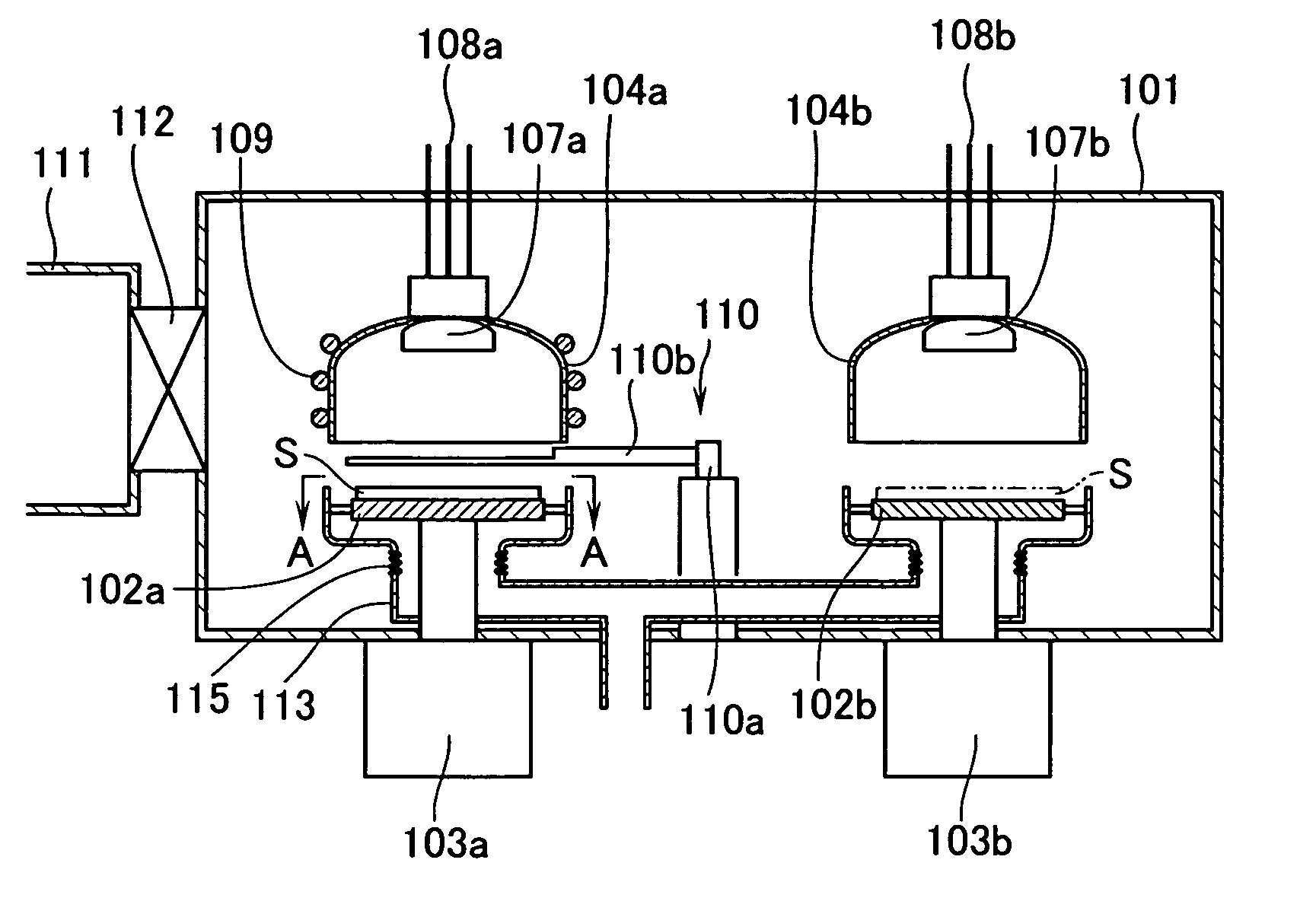
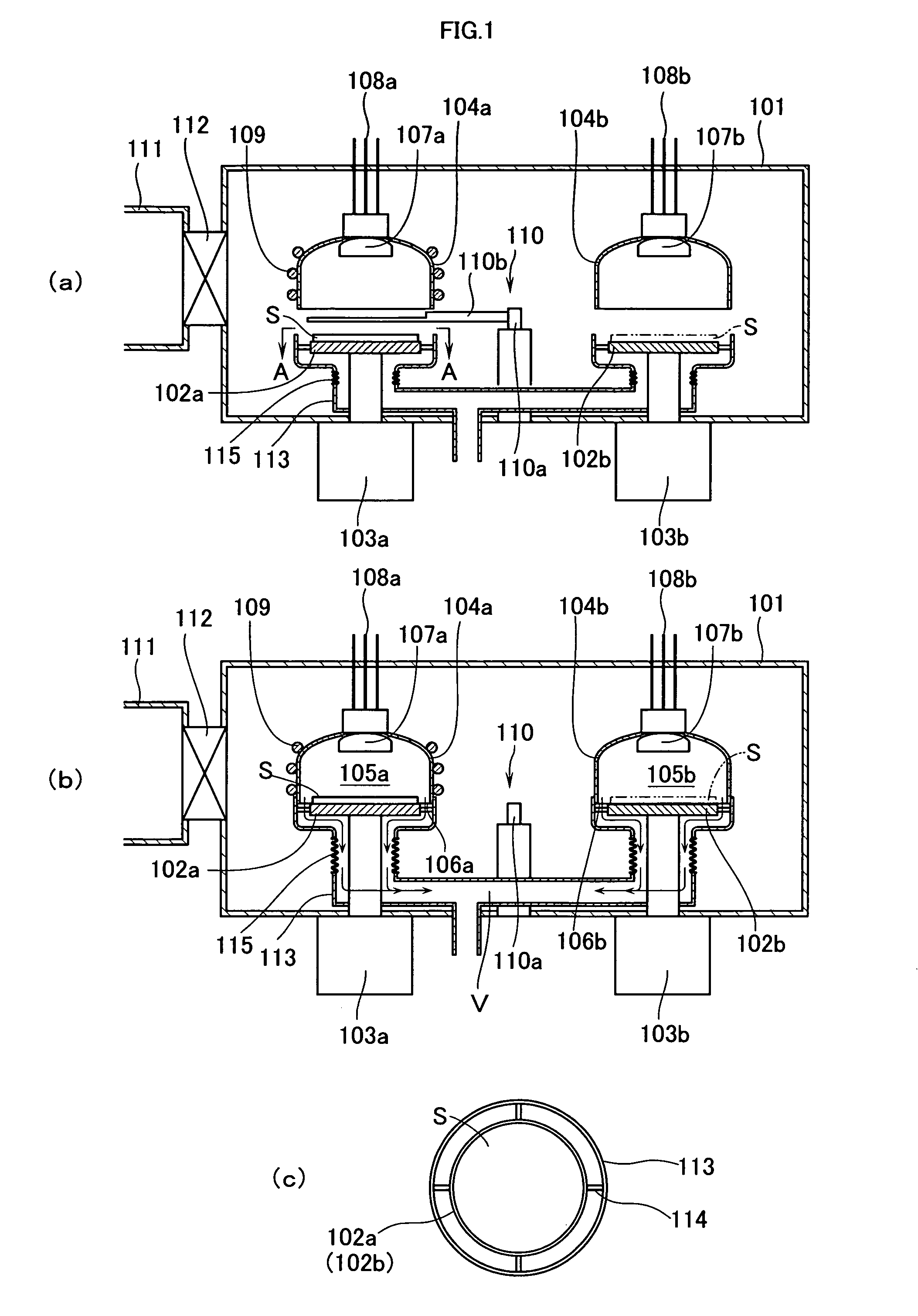
[0044] First of all, an embodiment of the vacuum film-forming apparatus (an atomic layer deposition apparatus (ALD apparatus)) according to the present invention will be described below in detail while referring to FIGS. 1(a) to (c) attached hereto. In FIG. 1, (a) is a cross sectional view schematically showing the structure of the apparatus observed during the step of conveying a subject on which a film is formed or a substrate; (b) is a cross sectional view schematically showing the structure of the apparatus observed when putting the film-forming step into practice; and (c) is a top plan view observed from the direction A-A specified in FIG. 1(a).

[0045] The vacuum film-forming apparatus 101 as shown in FIG. 1 is connected to an evacuation means (not shown) such as a turbo-type molecular pump or a rotary pump such that any suitable degree of vacuum (for instance, 1×10⁻⁶ Torr) can be established in the interior of the film-forming apparatus. A plurality of substrate stages 102a an...


PUM

PropertyMeasurementUnit
Sizeaaaaaaaaaa
Shapeaaaaaaaaaa
Circumferenceaaaaaaaaaa

Abstract

A vacuum film-forming apparatus comprising substrate stages; vacuum chamber-forming containers opposed to the stages; a means for moving the substrate between the stages; and gas-introduction means connected to every containers, wherein one of the stage and the container is ascended or descended towards the other to bring the upper face of the stage and the opening of the container into contact with one another so that vacuum chambers can be formed and that a raw gas and/or a reactant gas can be introduced into each space of the chamber through each gas-introduction means to carry out either the adsorption or reaction step for allowing the raw gas to react with the reactant gas. The apparatus permits the independent establishment of process conditions for the adsorption and reaction processes and the better acceleration of the reaction between raw and reactant gases to give a film having excellent quality and the apparatus can be manufactured at a low cost.

Description

BACKGROUND OF THE INVENTION [0001] 1. Field of the Invention [0002] The present invention relates to a vacuum film-forming apparatus or device, in particular, to a vacuum film-forming apparatus (an atomic layer deposition apparatus), which forms a thin film according to the ALD technique (Atomic Layer Deposition Technique). [0003] 2. Description of the Prior Art [0004] Recently, the patterns of semiconductor integrated circuits have increasingly been finer and it has correspondingly been devised that fine contact holes, trenches and other similar structures having high aspect ratios have been filled up with a distributing wire material such as Cu and / or Al. If the aspect ratio increases in this manner, it would be difficult to fill up such holes and / or trenches with a conductive film in a good or high coverage. [0005] When using, for instance, Cu as a principal distributing wire material in the case of the foregoing embedded distributing wire structure, deposited Cu may easily diffu...

Claims


Application Information

Patent Timeline
IPC IPC(8): C23C14/00C23C16/00C23C16/02C23C16/34C23C16/38C23C16/44C23C16/455C23C16/54
CPCC23C16/0236C23C16/34C23C16/38C23C16/44Y10S414/139C23C16/45525C23C16/45536C23C16/45551C23C16/54C23C16/4405H01L21/20
Inventor HATANAKA, MASANOBUISHIKAWA, MICHIOLIM, SE-JUNAKAMURA, FUMIO
Owner ULVAC INC
Why Eureka
Try Eureka