Ultraviolet sterilization device

Inactive Publication Date: 2005-12-08
MONESSEN HEARTH SYST
View PDF9 Cites 30 Cited by
  • Summary
  • Abstract
  • Description
  • Claims
  • Application Information

AI Technical Summary

Benefits of technology

[0010] The present invention relates to an apparatus for use in water purification having improved effectiveness through the employment of a self-cleaning mechanism to maintain a desired degree of transmittance of ultraviolet radiation through an ultraviolet transparent quartz tube for ultraviolet lamps. The apparatus includes an efficient arrangement of light shielding baffles to protect UV sensitive components from the UV light. The apparatus is provided as a component in a housing having a modular design. Aspects of the present invention function to enhance the efficiency and consistency of the apparatus by controlling heat.
[0011] According to an aspect of the invention, an apparatus is provided that employs plates formed of a material impervious to ultraviolet radiation on all wavelengths, which acts to shield other components such as rubber and polymer-based seals and bearings from the harmful effects of direct ultraviolet irradiation. The apparatus includes a tubular body, which may be a quartz tube for conducting fluid therethrough having an internally mounted wiper for the continuous cleaning of an inside surface of the tubular body. Potentially biologically contaminated fluids are irradiated by at least one radiation source including at least one elongated discharge lamp mounted externally with respect to the fluid-conducting tubular body. The wiper is formed of stainless steel or other UV-impervious materials. The wiper may include a rectangular elongate blade mounted to a shaft extending along the long axis of the apparatus. The blade may be provided with one or more holes for increased light penetration and f

Problems solved by technology

One important limitation to this type of device is that the exterior surface of the quartz tube becomes fouled with inactivated biological contaminants in the water as well as minerals at least in part due to a photochemical reaction upon exposure to the light of the lamp.
The foulants cause a reduced transmission of ultraviolet light through the light transmission tube, which results in a reduced efficacy of the device.
To reduce maintenance and downtime, automatic wiping mechanisms have been tried on these systems with limited success.
This costly mechanism is difficult to actuate and to provide adequate sealing for the power transmission shaft connected to the motor outside of the steel cylinder of the pressure vessel.
Cleaning the tube in this manner is cumbersome and compromises the irradiation dosage of the device because the gap between the outer wall of the quartz sheaf and the inner wall of the pressure vessel must be increased to accommodate the wiper resulting in a larger dosage gradient across the laminar fl

Method used


Image

  • Ultraviolet sterilization device
  • Ultraviolet sterilization device
  • Ultraviolet sterilization device

Examples


Embodiment Construction

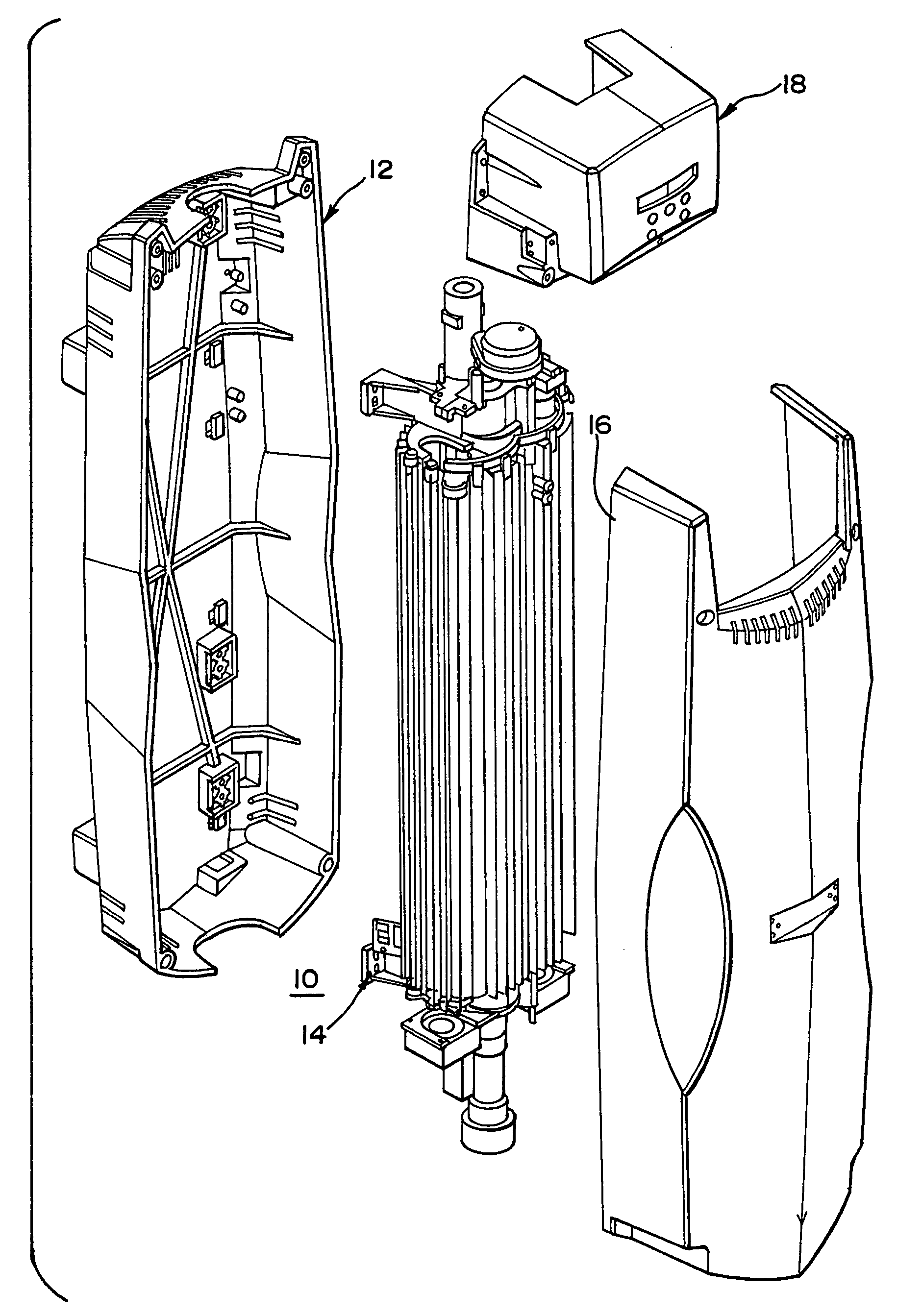
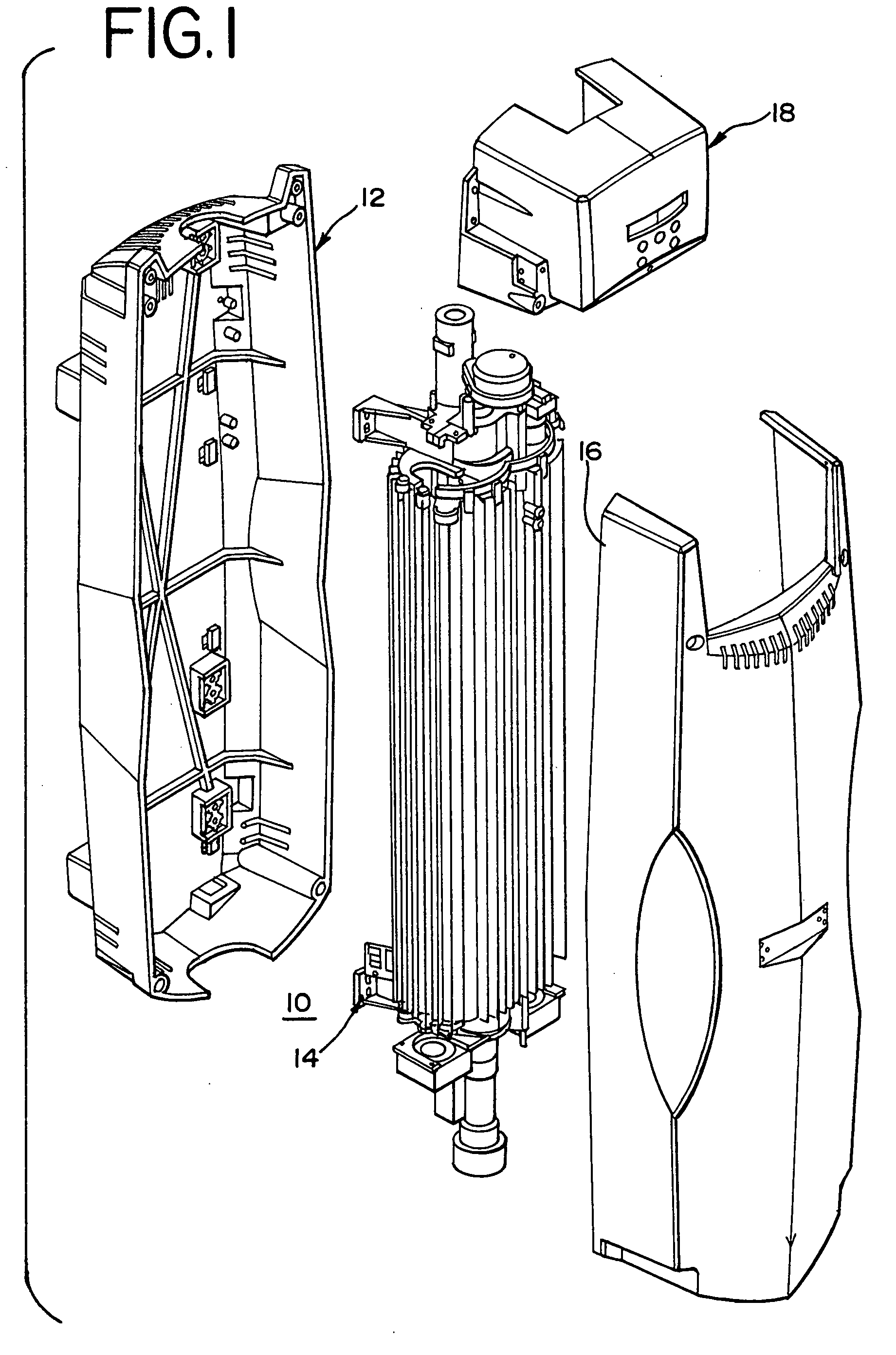
[0023]FIG. 1 illustrates one embodiment of subassemblies of an apparatus 10 according to the present invention. A back body housing 12 defines a chamber in which a UV chamber subassembly 14 is positioned. A front body cover 16, when fastened to the back body housing 12 effectively encloses the UV chamber subassembly 14. An electronic subassembly 18 fastens to an upper end of the back and front body covers 12, 16. It will be understood that reasonably different arrangements which function in an equivalent fashion and different appearances of the subassemblies are contemplated by the present invention. Furthermore, it will be understood that it is considered within the current state of the art for one to design appropriate circuitry to provide the functionality of the apparatus of the present invention.

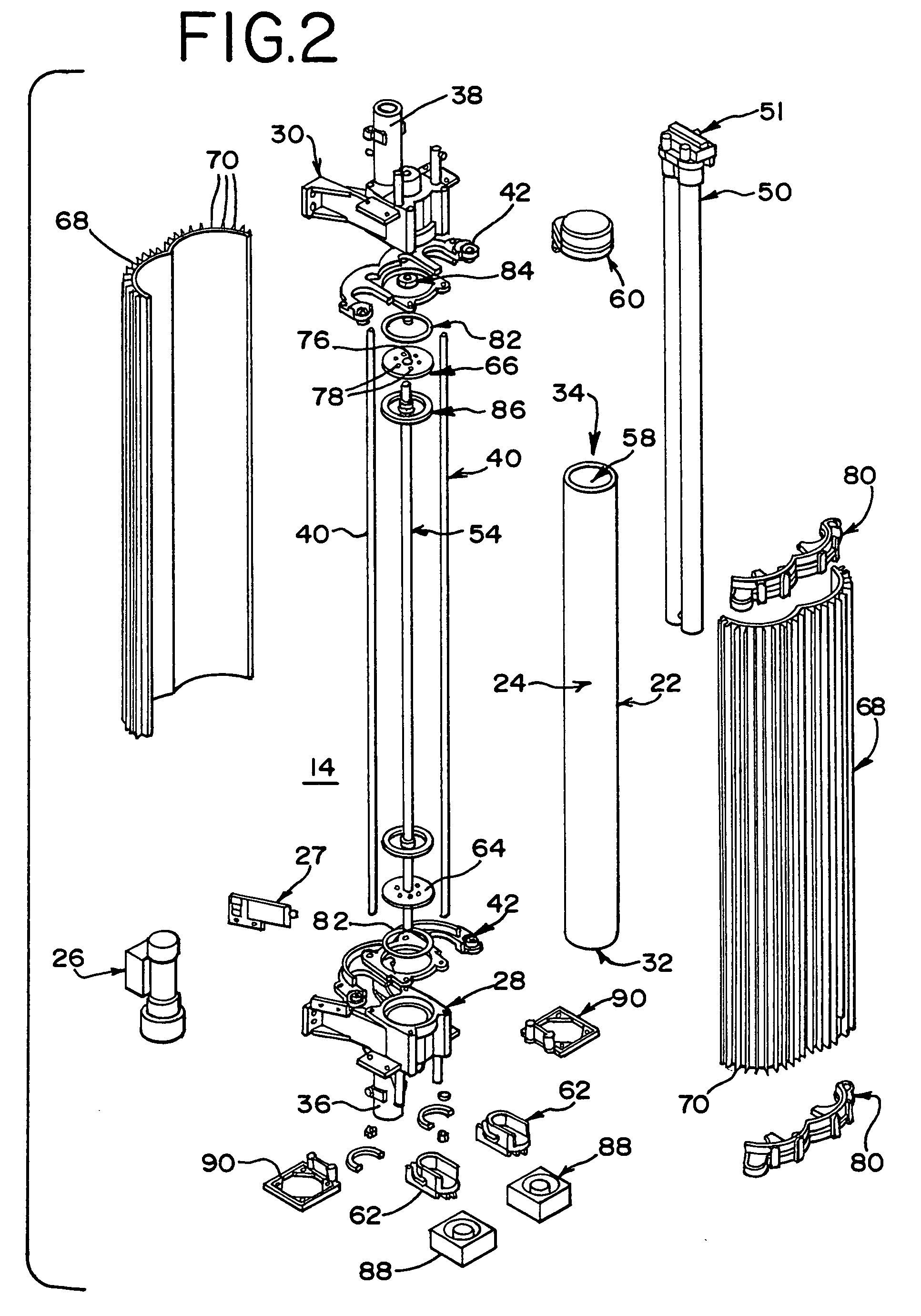
[0024] An embodiment of the UV chamber subassembly 14 according to the present invention is illustrated in FIG. 2. It will be understood that the elements of the subassembly 14, descri...


PUM

PropertyMeasurementUnit
Electrical conductoraaaaaaaaaa
Permeabilityaaaaaaaaaa
Heataaaaaaaaaa

Abstract

An apparatus for irradiation of a fluid with UV light includes a tubular body consisting of UV-permeable material. The body includes a fluid chamber and openings for passage of fluid. A UV source is provided to subject the chamber to the UV light. Light baffles define an irradiated section of the chamber to prevent light penetration beyond the irradiated section while permitting the fluid to flow through. The apparatus is provided as a component in a housing having a modular design. The modules include a back cover for surface mounting. The body is mounted to the back cover. An inner cover is attached to the back cover. The inner cover includes the UV source and modular electronics. A front cover is attached to the inner and back cover. Heat sink elements are provided to control the heat produced in the apparatus.

Description

FIELD OF THE INVENTION [0001] This invention relates to an apparatus for subjecting fluids to ultraviolet (UV) light. The apparatus may be used for water sterilization and is intended for Point-of-Entry use. BACKGROUND OF THE INVENTION [0002] Point-of-Entry ultraviolet water sterilization devices typically include a pressure vessel including a stainless steel cylinder enclosing a smaller concentric quartz light transmission tube. Within the quartz tube is a tubular discharge lamp emitting light with wavelengths typically centered around 254 nm, which is referred to as ultraviolet light or ultraviolet radiation. Ultraviolet (UV) light represents a section of the overall electromagnetic spectrum of light, extending from the blue end of the visible at about 400 nm to a region of about 100 nm. [0003] Water to be exposed to the light from the lamp is passed between the interior surface of the steel cylinder and the exterior surface of the light transmission tube. One important limitation...

Claims


Application Information

Patent Timeline
IPC IPC(8): C02F1/32
CPCC02F1/325C02F2209/40C02F2201/326C02F2201/3228
Inventor ZAGROBELNY, RICHARD
Owner MONESSEN HEARTH SYST
Why Eureka
Try Eureka