Directly modulated laser optical transmission system

a laser optical transmission and modulation technology, applied in the direction of electromagnetic transmission, electromagnetic transceivers, semiconductor lasers, etc., can solve the problems of the use of amplitude modulation may suffer from the noise and nonlinearity of the optical source, and the external modulation techniques are complex and expensive, etc., to achieve the effect of reducing the frequency independent component of the distortion, reducing the distortion of the signal, and reducing the product of the second and higher

Inactive Publication Date: 2005-12-08
EMCORE INC
View PDF46 Cites 132 Cited by
  • Summary
  • Abstract
  • Description
  • Claims
  • Application Information

AI Technical Summary

Benefits of technology

[0028] Briefly, and in general terms, the present invention provides an optical transmitter for generating a modulated optical signal for transmission over a dispersive fiber optic link to a remote receiver having an input for receiving a broadband analog radio frequency signal input; a semiconductor laser for producing an optical signal; and a modulation circuit for directly modulating the laser with the analog signal, including a predistortion circuit for reducing the distortion in the signal present at the receiver end of the fiber optic link.
[0029] In another aspect, the present invention provides an optical transmission system for use over dispersive fiber optic links including an optical transmitter with analog signal input; a low chirp laser; a modulation circuit for directly modulating the laser, and a predistortion circuit for reducing the frequency independent component of the distortion of the semiconductor laser.
[0030] In another aspect, the present invention further provides a low-cost direct modulation technique, preferably including a predistortion circuit for reducing second and higher order distortion products produced by a nonlinear device such as a laser.
[0032] In another aspect of the invention, there is provided a predistortion circuit for reducing distortion in the transmission of analog signals that splits an input modulation signal into two electrical paths, one primary and one secondary. A predistortion amplifier on the secondary path generates second order or higher order intermodulation distortion products of the input signal. The distortion so generated, or predistortion, is adjusted to be substantially equal in magnitude and opposite in sign to the distortion inherent in a nonlinear modulation device to which the signal is applied. The predistortion signal is adjusted in amplitude and phase to match the frequency dependence of the distortion by the nonlinear device. The phase of the signals are synchronized by a delay or phase adjustment element in one of the electrical paths. The primary and secondary signals are then recombined to produce a single modulation signal including intermodulation product distortion. Thus, the predistortion circuit largely linearizes the transmission of modulating signals by canceling distortion inherent in nonlinear transmitting devices, making the analog signals suitable for transmission over dispersive fiber optic links.

Problems solved by technology

Although such analog transmission techniques have the advantage of substantially smaller bandwidth requirements than digital transmission, such as digital pulse code modulation, or analog or pulse frequency modulation, the use of amplitude modulation may suffer from noise and nonlinearity of the optical source.
For applications in metro and long haul fiber transmission links, the low loss of the link requires that externally modulated 1550 nm lasers be used, but such external modulation techniques are complex and expensive.
One of the difficulties in designing an analog system at 1550 nm is that suitable low chirp lasers for use at 1550 nm are not known in the prior art.
Distortion inherent in certain analog transmitters prevents a linear electrical modulation signal from being converted linearly to an optical signal, and instead causes the signal to become distorted.
These effects are particularly detrimental to multi-channel video transmission, which requires excellent linearity to prevent channels from interfering with each other.
Linearization of optical and other nonlinear transmitters has been studied for some time, but proposed solutions suffer from practical disadvantages.
Most applications discussed above have bandwidths, which are too large for many practical implementations.
Feedforward techniques require complex system components such as optical power combiners and multiple optical sources.
Quasi-optical feedforward techniques suffer from similar complexity problems and further require extremely well matched parts.
However, the method suffers from crudeness because nonlinear devices frequently have amplitude and phase distortion characteristics dependent on the frequency of the modulating signal.
Neglecting to correct for the frequency dependence of the distortion leads to a result that may be quite tolerable for many systems and for signals with relatively narrow bandwidth.
However, they become particularly troublesome when converting an electrical TV signal to an optical signal for cable transmission.
Although multi-path predistortion circuits can be used in a broad variety of applications, the design of these circuits is relatively complex.
This complexity manifests itself in circuits that are often too expensive for applications needing only a modest degree of linearization.
Many non-linear transmitters or amplifiers, however, contain reactive elements such as inductances, capacitances or delays, which cause the device to produce distortion depending on the input and output frequencies and the distortion frequencies.
However, the circuit disclosed by Nazarathy may not have the right phase or frequency dependence for each set of input frequencies, to be substantially the same in magnitude and opposite in sign to the distortion produced by the non-linear device.

Method used


Image

  • Directly modulated laser optical transmission system
  • Directly modulated laser optical transmission system
  • Directly modulated laser optical transmission system

Examples


Embodiment Construction

[0042] Details of the present invention will now be described, including exemplary aspects and embodiments thereof. Referring to the drawings and the following description, like reference numbers are used to identify like or functionally similar elements, and are intended to illustrate major features of exemplary embodiments in a highly simplified diagrammatic manner. Moreover, the drawings are not intended to depict every feature of actual embodiments nor the relative dimensions of the depicted elements, and are not drawn to scale.

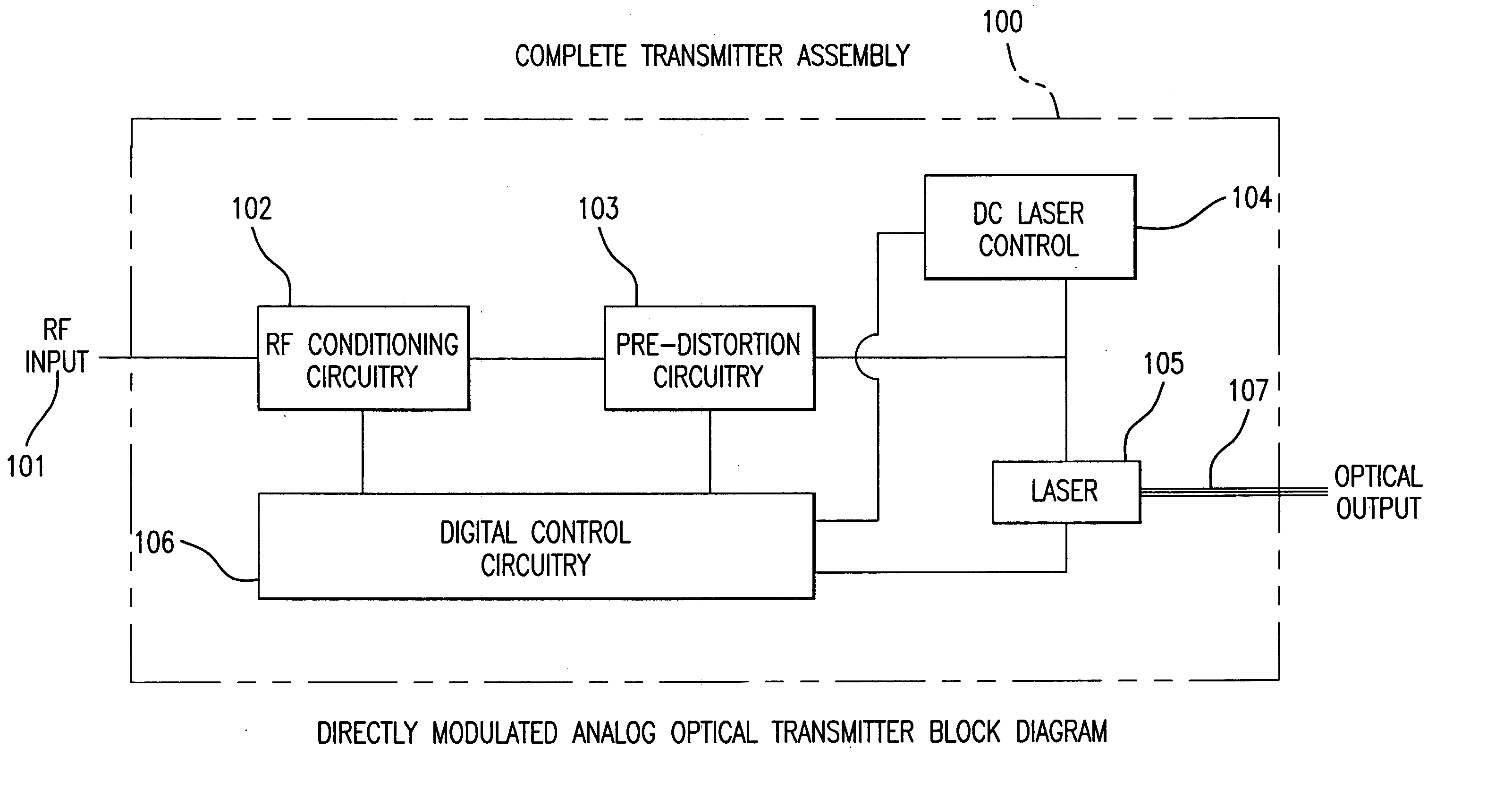
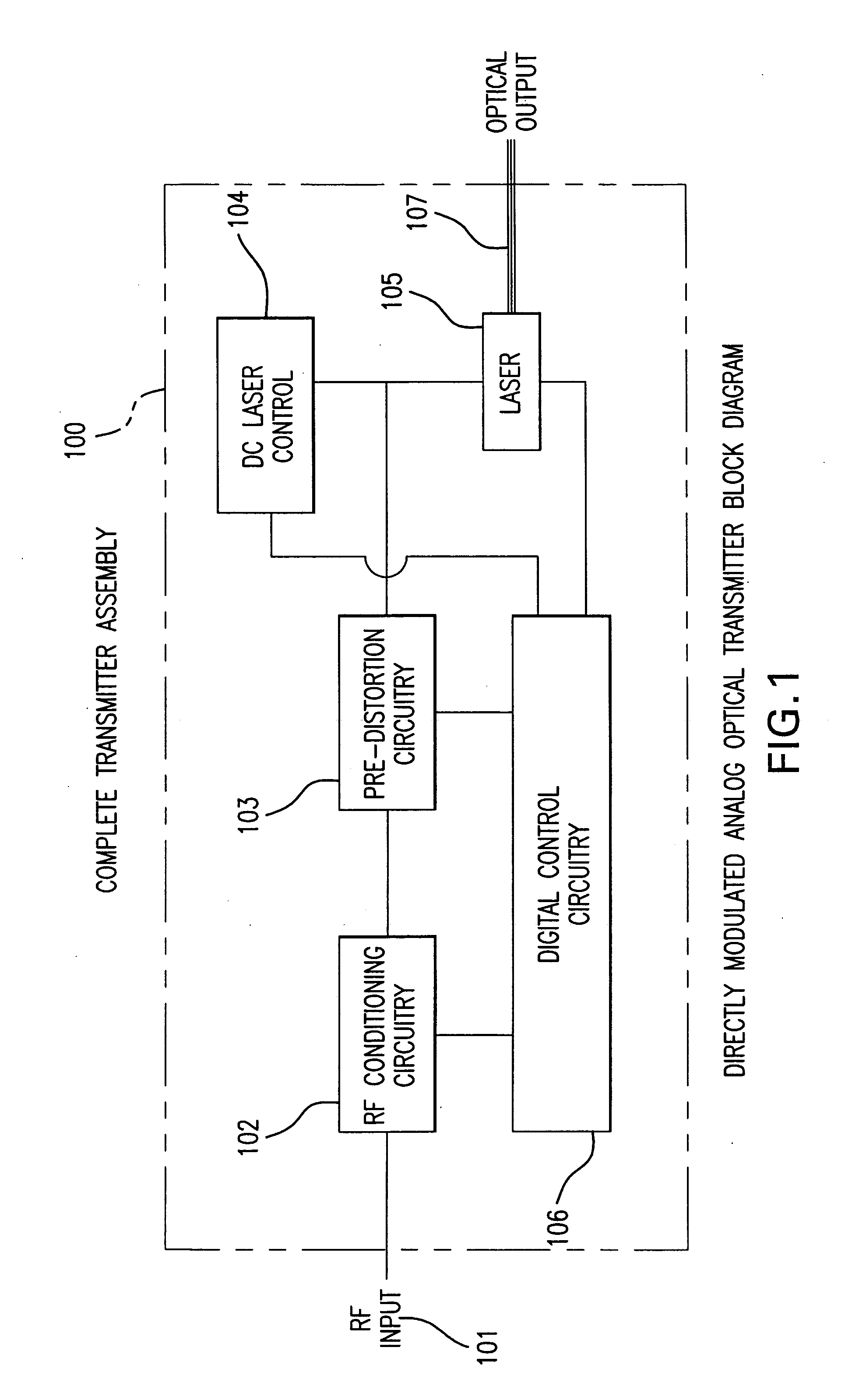
[0043]FIG. 1 is a highly simplified block diagram of the optical transmission system 100 according to the present invention. There is shown an analog RF signal input source 101, such as a broadband signal including a plurality of distinct information-containing communications signals or channels. The RF input is applied to RF conditioning circuitry 102 that performs . . . . The output of the RF conditioning circuitry 102 is applied to a pre-distortion ci...


PUM


Abstract

An optical transmitter for generating a modulated optical signal for transmission over dispersive fiber optic links in which a broadband analog radio frequency signal input is applied to a modulation circuit for directly modulating a semiconductor laser with the analog signal input. The transmitter may further include a temperature sensor in proximity to the laser and a negative feedback control circuit coupled to the temperature sensor for adjusting the temperature of the laser in response to an output characteristic of the laser, such as linearity.

Description

REFERENCE TO RELATED APPLICATIONS [0001] This application is related to U.S. patent application Ser. No. 10 / 946,056 filed Sep. 21, 2004, and assigned to the common assignee. [0002] This application claims the benefit of U.S. Provisional Patent Application No. 60 / 554,523 filed Mar. 19, 2004.BACKGROUND OF THE INVENTION [0003] 1. Field of the Invention [0004] This invention relates to an optical transmission system for analog signals, and in particular to a directly modulated solid-state laser. More particularly, the invention relates to the use of an electronic circuit for providing a linear output from an amplitude modulated transmission device such as a semiconductor laser which has an output distorted from its input due to inherent nonlinearity. The distortion of the nonlinear device is compensated by applying a predistorted signal to the input of the nonlinear device. The predistortion is chosen such that the distortion of the nonlinear device restores the undistorted signal, enab...

Claims


Application Information

Patent Timeline
Patent Type & Authority Applications(United States)
IPC IPC(8): H04B10/155H04B10/04H04B10/26H04B10/18H04B10/06H04B10/02H04B10/152H04B10/142H01S5/062H04B10/14H04B10/28H04B10/43
CPCH04B10/504H04B10/58H04B10/5057H01S5/0427H01S5/06213H01S5/06246H01S2301/03H04B10/2537H04B10/25751H01L21/67144
Inventor IANNELLI, JOHN
Owner EMCORE INC
Why Eureka
Try Eureka