Plasma processing apparatus and method

a processing apparatus and plasma technology, applied in the field of plasma processing apparatus and plasma processing method, can solve the problems of becoming more difficult to choose the optimal material and shape of the focus ring, and achieve the effect of superior surface uniformity

Inactive Publication Date: 2005-12-15
TOKYO ELECTRON LTD
View PDF11 Cites 30 Cited by
  • Summary
  • Abstract
  • Description
  • Claims
  • Application Information

AI Technical Summary

Benefits of technology

[0009] It is, therefore, an object of the present invention to provide plasma processing apparatus and method capable of optimizing the plasma state by controlling the temperature difference between a substrate and a ring portion surrounding the substrate, thereby performing a plasma process on the substrate with superior in-surface uniformity.
[0014] In accordance with a fourth aspect of the present invention, there is provided a plasma processing method using a plasma processing apparatus having a ring portion disposed to surround a mounting table in a processing chamber, the method including the following sequential steps of mounting a dummy substrate on the mounting table and generating a plasma under more severe conditions than those in an actual plasma processing which is performed on a product substrate such that temperature of the ring portion is higher than the product substrate in the actual plasma processing, thereby increasing the temperature of the ring portion; replacing the dummy substrate on the mounting table with the product substrate; and supplying a processing gas in the processing chamber and converting the processing gas into a plasma by applying a high frequency power to perform the actual plasma processing on the product substrate.
[0015] In accordance with the present invention, the temperature of the ring portion is set to be higher than that of the substrate, whereby the density of active species near the peripheral portion of the substrate is lower than that of active species in the inner region. Accordingly, even though the density of active species near the peripheral portion of the substrate tends to become higher than that of active species in the inner region due to, e.g., the draft of exhausted gas, the temperature difference suppresses it to thereby maintain a lower density difference. As a result, the substrate can be plasma processed with superior in-surface uniformity.

Problems solved by technology

Due to the uniformity requirement, it is becoming more difficult to choose the optimal material and shape of the focus ring 13 for controlling the plasma density near the peripheral portion of the wafer 100.

Method used


Image

  • Plasma processing apparatus and method
  • Plasma processing apparatus and method
  • Plasma processing apparatus and method

Examples


example 1

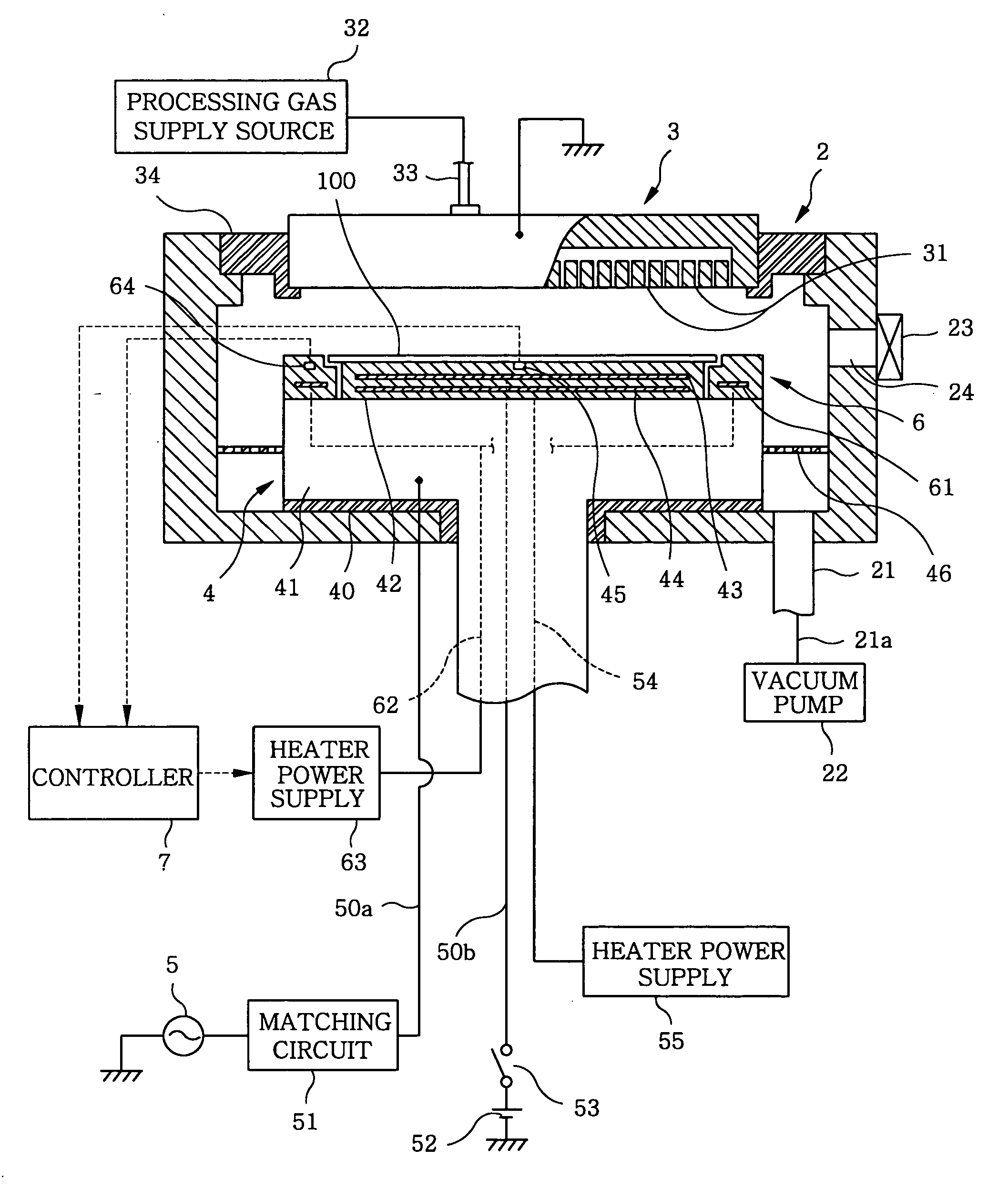
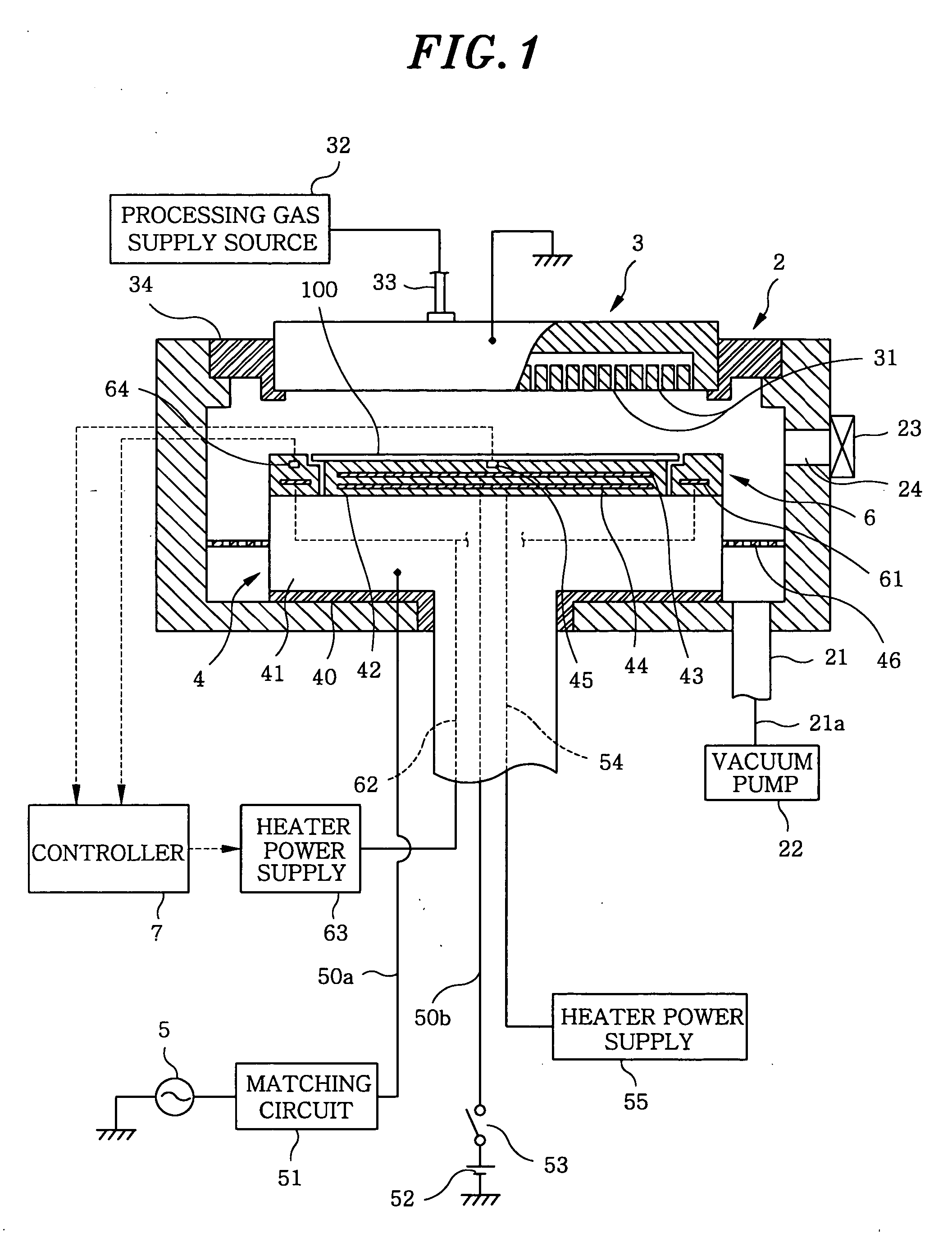
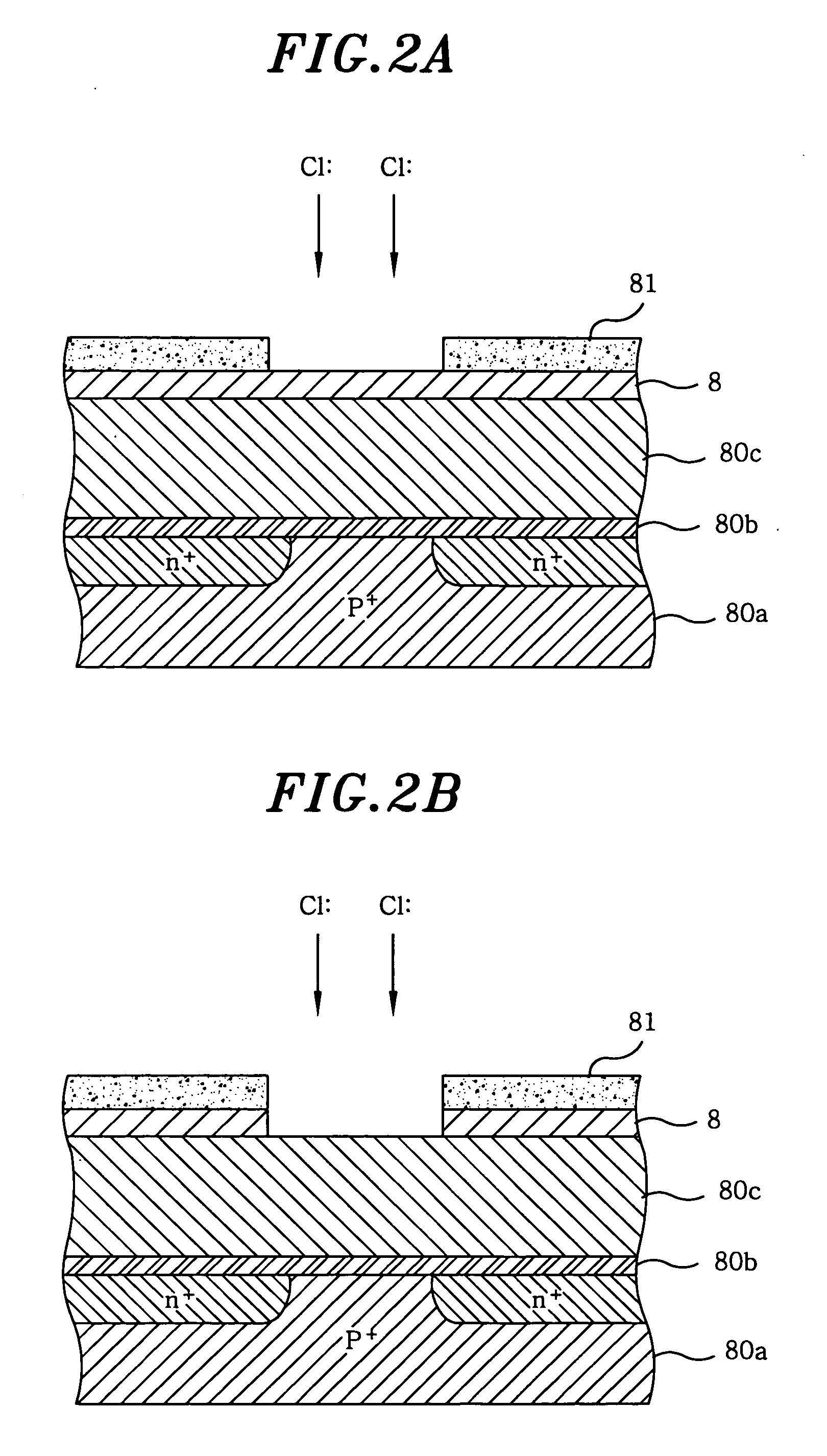
[0050] In this example, the above-mentioned preliminary heating is performed by using the apparatus shown in FIG. 5 while a temperature difference of 50° C. is established between the wafer 100 and the ring member 6. Specific process conditions will be listed below. The film thicknesses of the wafer 100 before and after an etching process are measured at intervals along the respective axes of X axis, Y axis, V axis and W axis equally spaced apart, intersecting at the center of wafer 100. FIG. 6 shows etching rates obtained by calculation at respective measurement points. [0051] Object to be etched: tungsten silicide [0052] Etching gas: Cl2 (150 sccm) and O2 (10 sccm) [0053] Pressure: 5 mTorr [0054] HF / LF power (for generating plasma / for bias) : 250 W / 200 W [0055] Magnetic field intensity: 56 G [0056] Temperature difference: 50° C. (temperature of ring member 6=126° C., temperature of wafer 100=76° C.)


PUM

PropertyMeasurementUnit
temperatureaaaaaaaaaa
widthaaaaaaaaaa
temperature detectoraaaaaaaaaa

Abstract

A plasma processing apparatus for converting a processing gas into a plasma by a high frequency power in a processing chamber and performing a plasma processing on a substrate mounted on a mounting table includes a ring portion disposed to surround the substrate on the mounting table, and a temperature control unit for establishing a temperature difference between the ring portion and the substrate, such that the ring portion is at least 50° C. higher than the substrate. Further, the processing gas generates chlorine radicals, and the temperature control unit is at least one of a heating unit for heating the ring portion and a cooling unit for cooling the mounting table.

Description

FIELD OF THE INVENTION [0001] The present invention relates to a plasma processing apparatus and a plasma processing method for performing a specified process, e.g., an etching process, on a substrate such as a semiconductor wafer by using plasma. BACKGROUND OF THE INVENTION [0002] In manufacturing semiconductor devices, in order to separate capacitors or elements, or otherwise to form contact holes, dry etching or film forming process using plasma has been performed on a substrate such as a semiconductor wafer (hereinafter, referred to as a “wafer”). As one of the apparatuses capable of performing such processes, a single wafer parallel plate type plasma processing apparatus is used, wherein a high frequency voltage is applied between an upper electrode and a lower electrode to generate plasma. [0003]FIG. 9 shows a schematic diagram of the above-mentioned plasma apparatus. To describe it briefly, in an sealed chamber 1 which is a vacuum chamber, an upper electrode 11 (also serving ...

Claims


Application Information

Patent Timeline
Patent Type & Authority Applications(United States)
IPC IPC(8): C23C16/00C23C16/458C23C16/52H01L21/00
CPCC23C16/4585C23C16/463C23C16/52H01L21/67248
Inventor UKEI, TOMOAKIHIGUCHI, KIMIHIROMATSUDO, TATSUODENPOH, KAZUKI
Owner TOKYO ELECTRON LTD
Why Eureka
Try Eureka