
Conveying method, conveyance apparatus, exposure apparatus, and device manufacturing method

Inactive Publication Date: 2005-12-15
CANON KK
View PDF10 Cites 9 Cited by
  • Summary
  • Abstract
  • Description
  • Claims
  • Application Information

AI Technical Summary

Benefits of technology

[0009] The present invention has been made in view of the situations mentioned above, and can provide a reliable substrate conveyance technique.
[0012] According to the present invention, a reliable substrate conveyance technique can be provided.

Problems solved by technology

However, in the above-mentioned conveying units, there has been a problem that an original plate (reticle) drops and is damaged during conveying.
That is, under a vacuum condition as in the EUV exposure system, even when the reticle bottom surface is vacuum-suctioned as disclosed in Japanese Patent Laid-Open No. 05-278813, the pressure difference is small so that sufficient adsorption power for conveying the reticle cannot be obtained.
The reticle used in the EUV exposure system is generally made of glass, so that by the electrostatic chuck as disclosed Japanese Patent Laid-Open No. 2001-315085, No. 2000-031252, and No. 2002-203837, sufficient adsorption power for conveying the reticle cannot be obtained.
Furthermore, since a conductive film as a pattern film is formed on the bottom surface of the reticle used for the EUV exposure system, although the conductive film can be chucked with the electrostatic chuck, the adsorption power is different depending on the film material and the film quality, so that the reticle may drop and be damaged during conveying.

Method used


Image

  • Conveying method, conveyance apparatus, exposure apparatus, and device manufacturing method
  • Conveying method, conveyance apparatus, exposure apparatus, and device manufacturing method
  • Conveying method, conveyance apparatus, exposure apparatus, and device manufacturing method

Examples


first embodiment

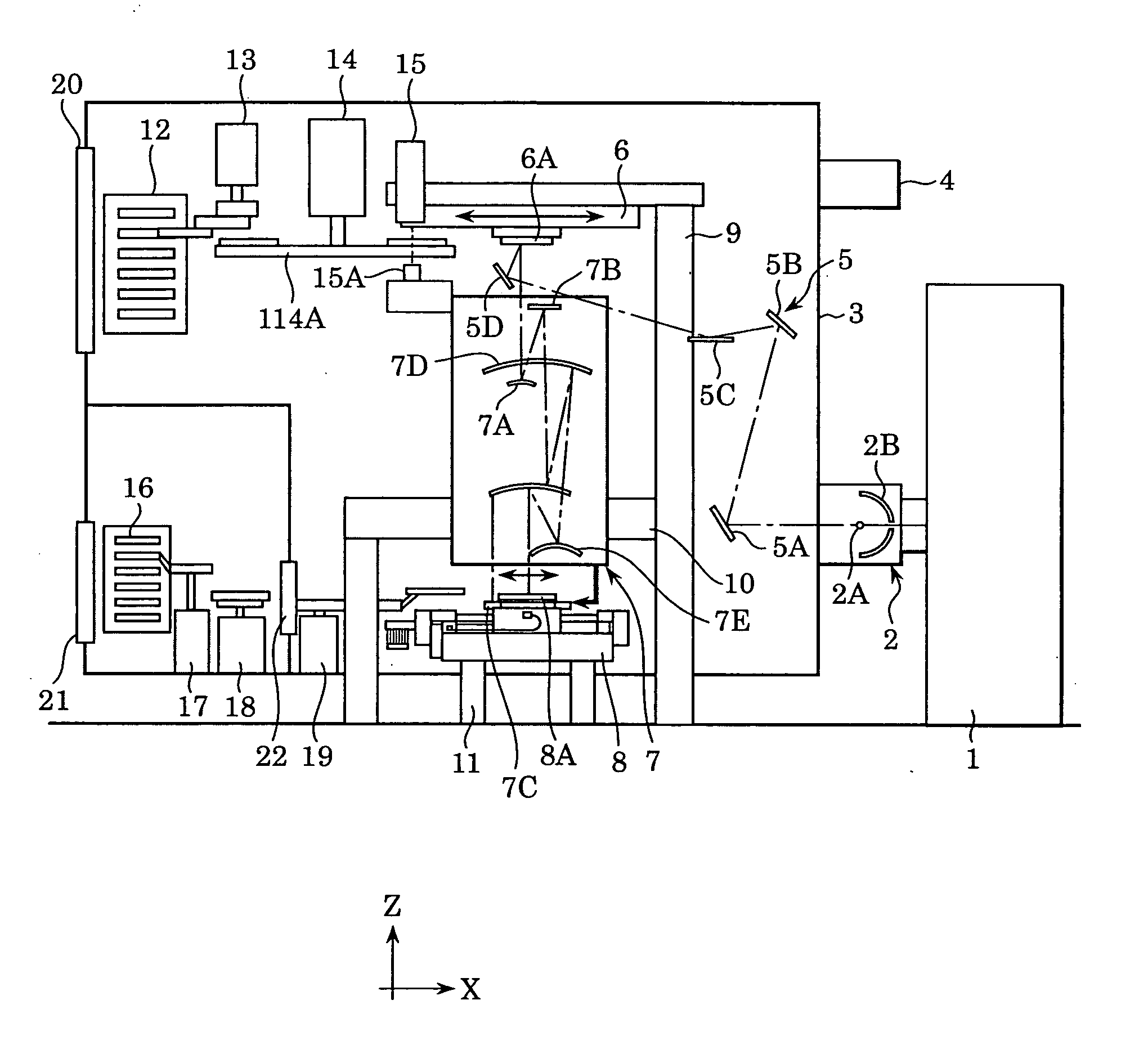
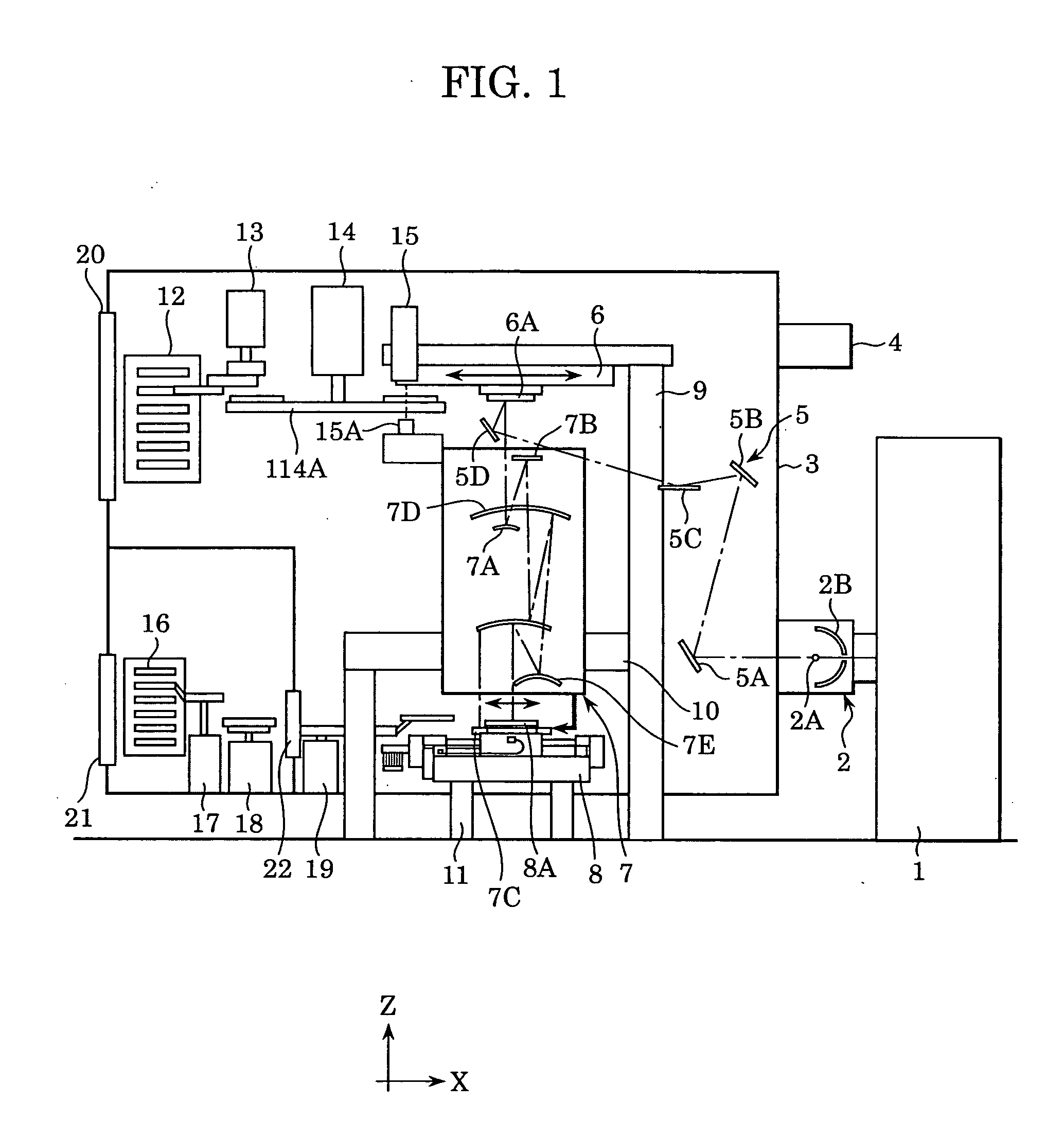
[0026]FIG. 1 is a schematic view of an exposure system having a reticle conveying hand under vacuum according to a first embodiment of the present invention. Referring to FIG. 1, a pumping laser 1 irradiates with laser a luminescent point of a light source where a light source material is evaporated, condensed, or atomized so as to make the light source material atoms radiate by plasma-exciting them. The pumping laser 1 uses a YAG (yttrium aluminum garnet) solid laser, for example.

[0027] A luminescent light source unit 2 for exposure has a structure maintained in vacuum inside, and numeral 2A denotes a luminescent point of the exposure light source (referred to as a light source below). A light source mirror 2B is arranged in a semicircular shape about the light source 2A for aligning spherical light from the light source 2A so as to condense and reflect it. To the light source 2A, a luminescent chemical element, such as liquefied Xe, atomized liquefied Xe, and Xe gas, is ejected f...

second embodiment

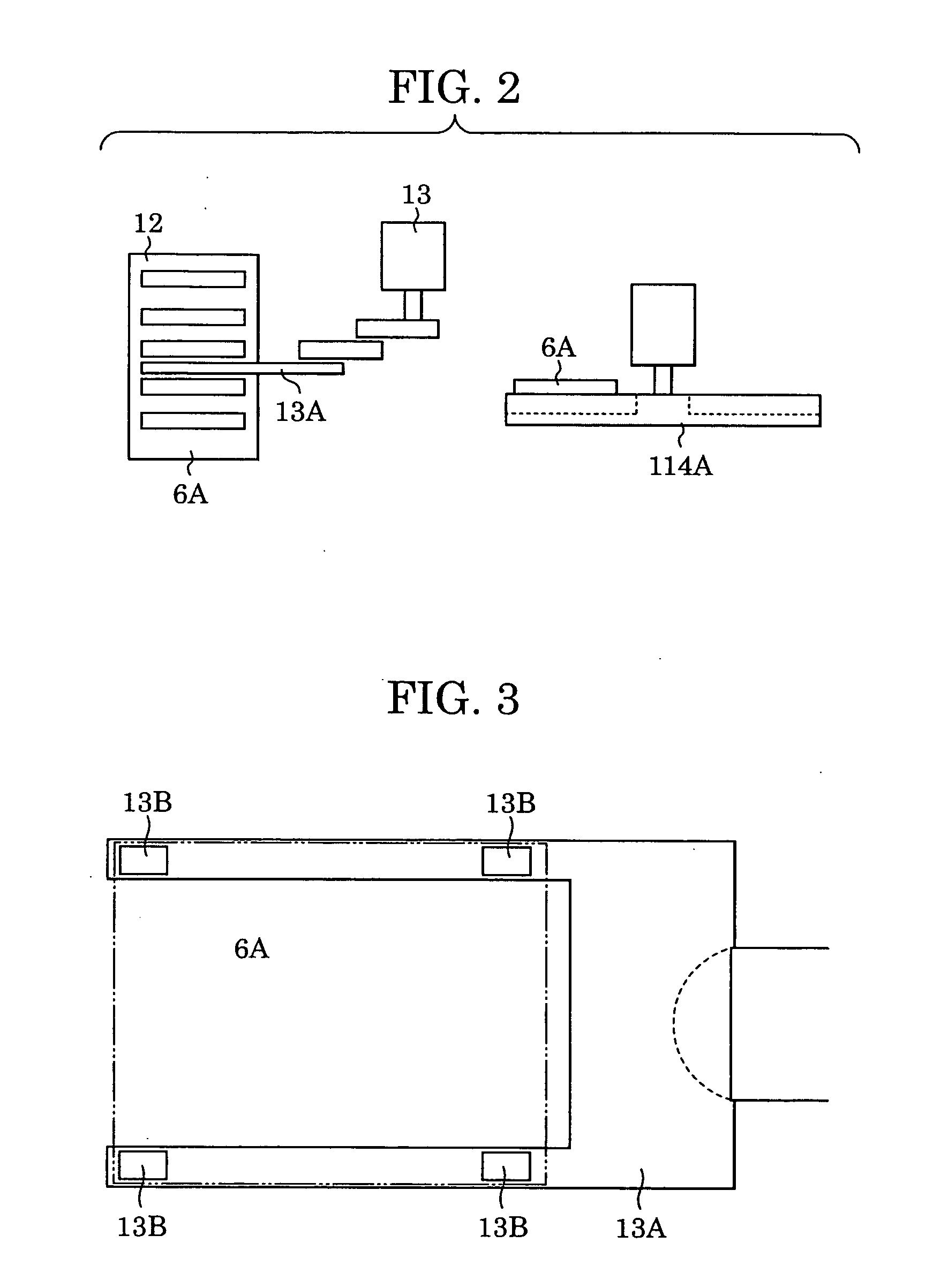
[0047]FIG. 6 is a schematic view of the electrostatic chuck pad 13B according to a second embodiment viewed laterally in one location. According to the second embodiment, a measuring electrode 13m is connected to the surface to be chucked via an elastic body 13e. To the measuring electrode 13m, wiring (not shown) is connected. By connecting the measuring electrode 13m to the surface to be chucked via the elastic body 13e, even if the surface to be chucked or the contact surface of the electrostatic chuck pad 13B is wavy or otherwise not flat, the measuring electrode 13m can be securely connected to the contact surface of the reticle 6A. Thus, at least one of the resistance, the dielectric constant, and the impedance of the surface to be chucked can be precisely measured.

third embodiment

[0048]FIG. 7 is a schematic view of the electrostatic chuck pad 13B according to a third embodiment viewed laterally in one location. The feature of the third embodiment is that the electrode of the electrostatic chuck pad 13B and the dielectric body 13d also serve as a measuring electrode for measuring the resistance, the dielectric constant, or the impedance of the surface to be chucked. Referring to FIG. 4B, since Cb and Rb denote the capacitance value and the resistance between the dielectric body 13d and the electrode, when measuring them in advance, Ca and Ra can be obtained by measuring the resistance, the dielectric constant, or the impedance of the entire that consists of Cb, Rb, Ca, and Ra. In the same way as in the first embodiment, in the relationship between the resistance, the dielectric constant, or the impedance of the surface to be chucked and the attraction force, the reticle peeling and the displacement of the reticle 6A due to a lateral force may be measured and ...


PUM


Abstract

A method of holding an object with an electrostatic chuck and conveying the held object includes steps of measuring a property of the object concerning an electrostatic attraction force generated between the object and the electrostatic chuck; and controlling a characteristic of conveyance of the object based on a measurement result in the measuring step.

Description

BACKGROUND OF THE INVENTION [0001] 1. Field of the Invention [0002] The present invention relates to a technique for holding a substrate with a dielectric chuck and conveying the held substrate. [0003] 2. Description of the Related Art [0004] For a semiconductor manufacturing process, a projection EUV exposure system is proposed in that a reticle pattern is projected and transcribed on a silicon wafer using EUV (extreme ultraviolet) light with a wavelength of 13 to 14 nm as light exposure. [0005] The disclosed EUV exposure system will be described with reference to FIG. 8. A reticle 306A has a device pattern drawn thereon. A vacuum chamber 303 forms a vacuum region. The reticle 306A is mounted on a reticle stage 306. A reticle lock 320 is used when the reticle 306A is conveyed into the vacuum chamber 303. A reticle changer hand 313 is used for conveying the reticle 306A. A reticle stocker 312 is for storing the reticle 306A within the vacuum region. [0006] In such a conventional exp...

Claims


Application Information

Patent Timeline
IPC IPC(8): B25J15/08B65G49/06B25J13/08B65G49/07G03F7/20H01H1/00H01L21/00H01L21/027H01L21/677H01L21/68H01L21/683H02H1/00
CPCG03F7/70708G03F7/7075H01L21/67242H01L21/6831H01L21/67259H01L21/67778H01L21/67253
Inventor KAMONO, TAKASHI
Owner CANON KK
Learn More