
Reflective mask useful for transferring a pattern using extreme ultra violet (EUV) radiation and method of making the same

a technology of ultraviolet radiation and reflective mask, which is applied in the field of semiconductor manufacturing, can solve the problems of increasing the complexity of manufacturing euv masks and difficult material selection

Active Publication Date: 2005-12-22
NXP USA INC
View PDF7 Cites 57 Cited by
  • Summary
  • Abstract
  • Description
  • Claims
  • Application Information

AI Technical Summary

Problems solved by technology

Since it is difficult to find a material that transmits EUV radiation when exposed to wavelengths in the EUV regime, EUV lithography operates in a reflective mode as opposed to the transmission mode.
Each additional layer that is formed and patterned requires deposition and patterning processes that increase the complexity of manufacturing the EUV mask.

Method used


Image

  • Reflective mask useful for transferring a pattern using extreme ultra violet (EUV) radiation and method of making the same
  • Reflective mask useful for transferring a pattern using extreme ultra violet (EUV) radiation and method of making the same
  • Reflective mask useful for transferring a pattern using extreme ultra violet (EUV) radiation and method of making the same

Examples


Embodiment Construction

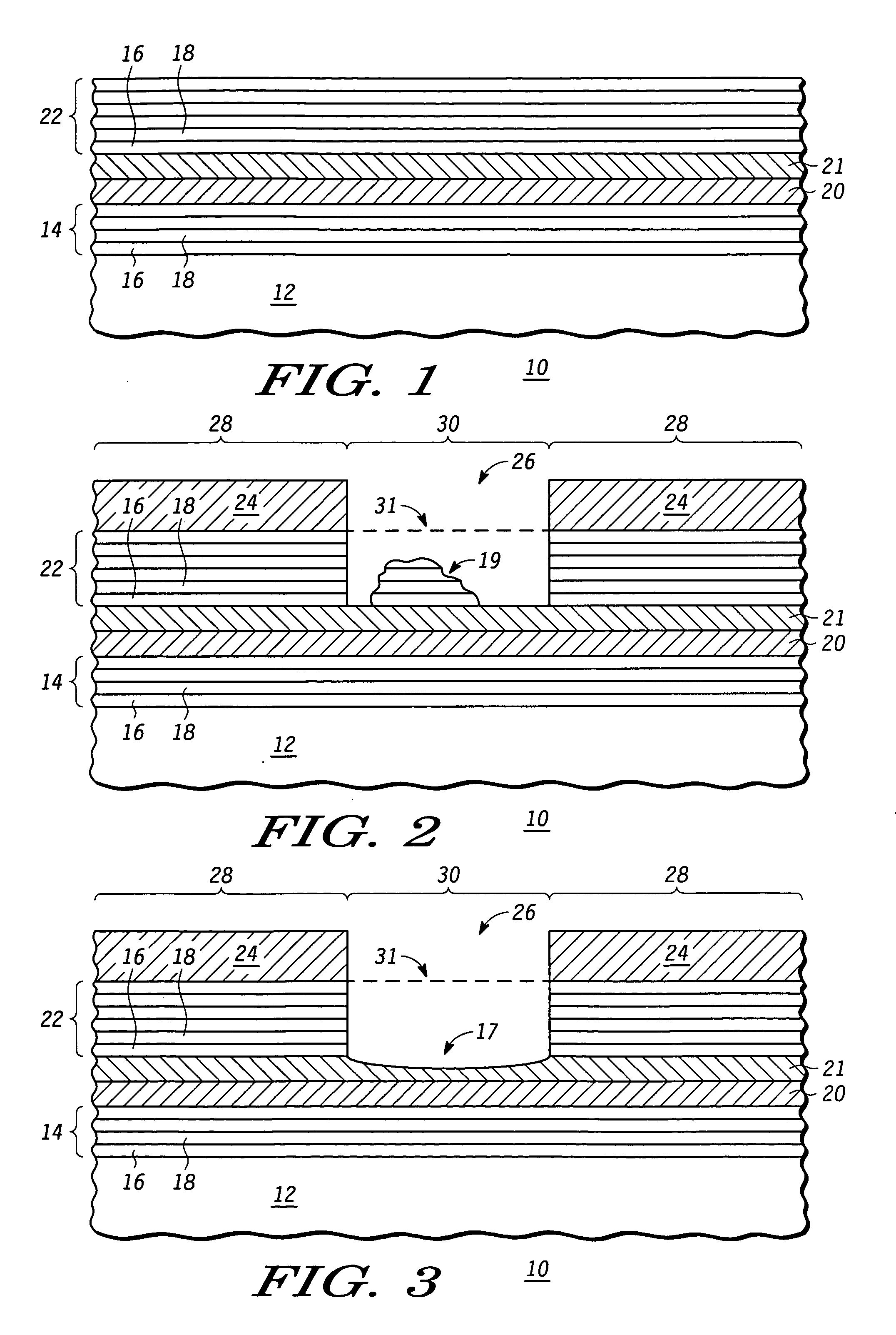
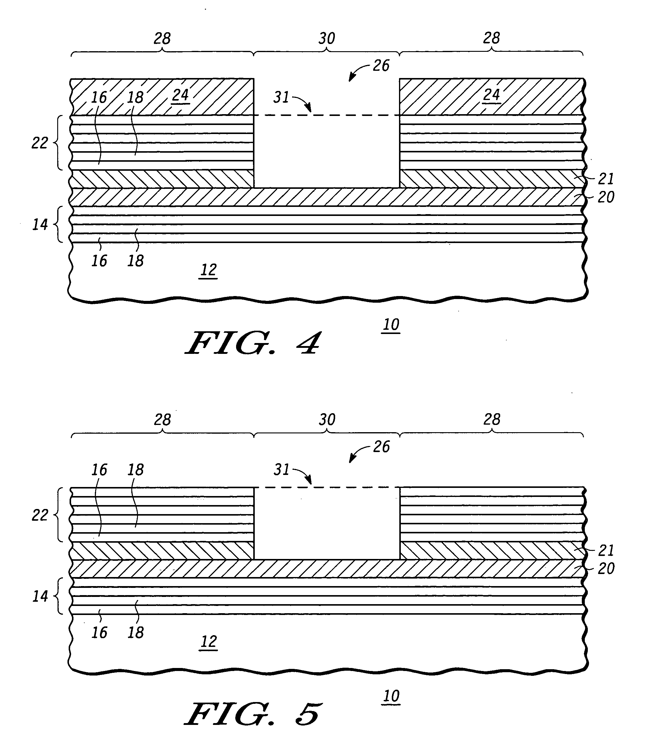
[0014] Instead of forming and patterning multiple layers over a reflective layer on a mask substrate (i.e., an additive mask fabrication process) to manufacture an EUV mask, it is desirable to pattern the reflective layer itself (i.e., a subtractive process). In a preferred embodiment, the reflective layer is a multilayer reflective stack of alternating materials. To pattern the reflective layer, an embedded layer used for etch stop purposes (EL 21), see FIG. 1, is embedded within the reflective layer. The reflective layer is patterned and etched to form an opening using a chemistry that is selective to the EL 21. Hence, the EL 21 is exposed once the opening is formed.

[0015] Both the HPSMs (hard phase shift masks) and the APSMs (attenuated phase shift masks) are reflective masks that utilize the phase information of light during exposure in a lithographic process. However, each of the APSM and HPSM form patterns using different parameters of light and thus, each mask has its own un...


PUM


Abstract

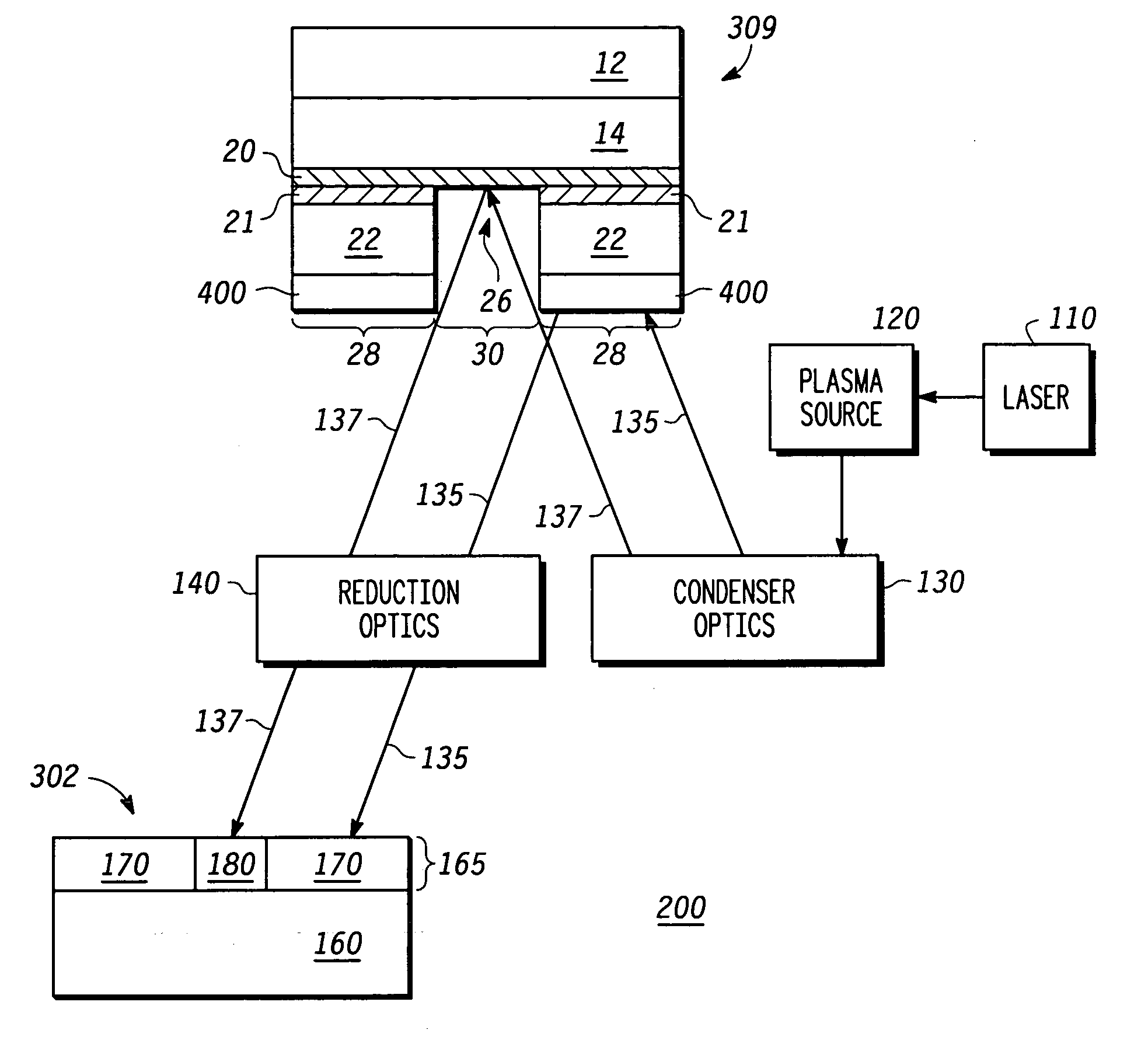
An EUV mask (10, 309) includes an opening (26) that helps to attenuate and phase shift extreme ultraviolet radiation using a subtractive rather than additive method. A first embedded layer (20) and a second embedded layer (21) may be provided between a lower multilayer reflective stack (14) and an upper multilayer reflective stack (22) to ensure an appropriate and accurate depth of the opening (26), while allowing for defect inspection of the EUV mask (10, 309) and optional defect repair. An optional ARC layer (400) may be deposited in region (28) to reduce the amount of reflection within dark region (28). Alternately, a single embedded layer of hafnium oxide, zirconium oxide, tantalum silicon oxide, tantalum oxide, or the like, may be used in place of embedded layers (20, 21). Optimal thicknesses and locations of the various layers are described.

Description

RELATED APPLICATIONS [0001] This application is related to U.S. Pat. No. 6,653,053 issued Nov. 25, 2003, entitled “Method of Forming a Pattern on a Semiconductor Wafer Using an Attenuated Phase Shifting Reflective Mask” and assigned to the current assignee hereof. This application is related to U.S. Pat. No. 6,673,520 issued Jan. 6, 2004, entitled “Method of Making an Integrated Circuit Using a Reflective Mask” and assigned to the current assignee hereof and incorporated herein by reference. This application is related to U.S. Pat. No. 6,596,465 issued Jul. 22, 2003, entitled “Method of Manufacturing a Semiconductor Component” and assigned to the current assignee hereof and incorporated herein by reference. This application is related to U.S. patent application Ser. No. 10 / 290,693 filed Nov. 8, 2002, entitled “Reflective Mask Useful for Transferring a Pattern Using Extreme Ultraviolet (EUV) Radiation and Method of Making the Same” and assigned to the current assignee hereof and inco...

Claims


Application Information

Patent Timeline
IPC IPC(8): G03C5/00G03F1/00G03F1/14G21K5/00
CPCB82Y10/00B82Y40/00G03F1/34G03F1/24G03F1/32G03F1/0084
Inventor HECTOR, SCOTT D.HAN, SANG-IN
Owner NXP USA INC
Learn More