Sensing system for monitoring the structural health of composite structures

a composite structure and sensor technology, applied in the field of sensor systems, can solve the problems of time-consuming and expensive monitoring of such structures, structural health of composite structures, and fractures and fatigue cracks of structural structures, and achieve the effects of high signal-to-noise ratio, easy adhesion, and controllable electrical and mechanical properties

Active Publication Date: 2005-12-29
UNIV OF DAYTON
View PDF17 Cites 137 Cited by
  • Summary
  • Abstract
  • Description
  • Claims
  • Application Information

AI Technical Summary

Benefits of technology

[0007] The present invention meets that need by providing a sensing system for monitoring the structural health of structures such as aircraft, bridges, and buildings which utilizes a sensor comprising a conductive ink having controllable electrical and mechanical properties. The sensor may be applied directly to a structure in any desired pattern as needed to monitor structural damage and strain of the structure. The sensor can be easily adhered to a variety of surfaces and may be tailored to detect damage at specific strain levels. The sensor has a very high signal to noise ratio, and utilizes conventional electrical resistance measurement conducive to multiplexing of plural sensors such as may be found in a sensing grid covering a large area. The sensor may be applied directly to a structure either manually or using automated equipment. The sensor has little effect on the surface profile of the structure, and adds very little weight to the structure.

Problems solved by technology

Over time, structures such as architectural and vehicular structures as well as aircraft, turbine blades, bridges, satellites, and ships can suffer from defects such as fractures and fatigue cracks.
Such defects, if undetected, may result in dangerous accidents.
Currently, the monitoring of such structures is time consuming and expensive.
Detecting hidden defects without disassembly of the structures is even more difficult when the structures cannot be disassembled, for example, in the case of buildings and bridges.
Conventional strain gages are known in the art but are not appropriate for monitoring the structural health of large structures as they cover a relatively small sensing area of up to several inches and require sophisticated calibration and electronics to monitor the strain.
In addition, such a sensor may be difficult to apply to rough or uneven surfaces.

Method used


Image

  • Sensing system for monitoring the structural health of composite structures
  • Sensing system for monitoring the structural health of composite structures
  • Sensing system for monitoring the structural health of composite structures

Examples


example 1

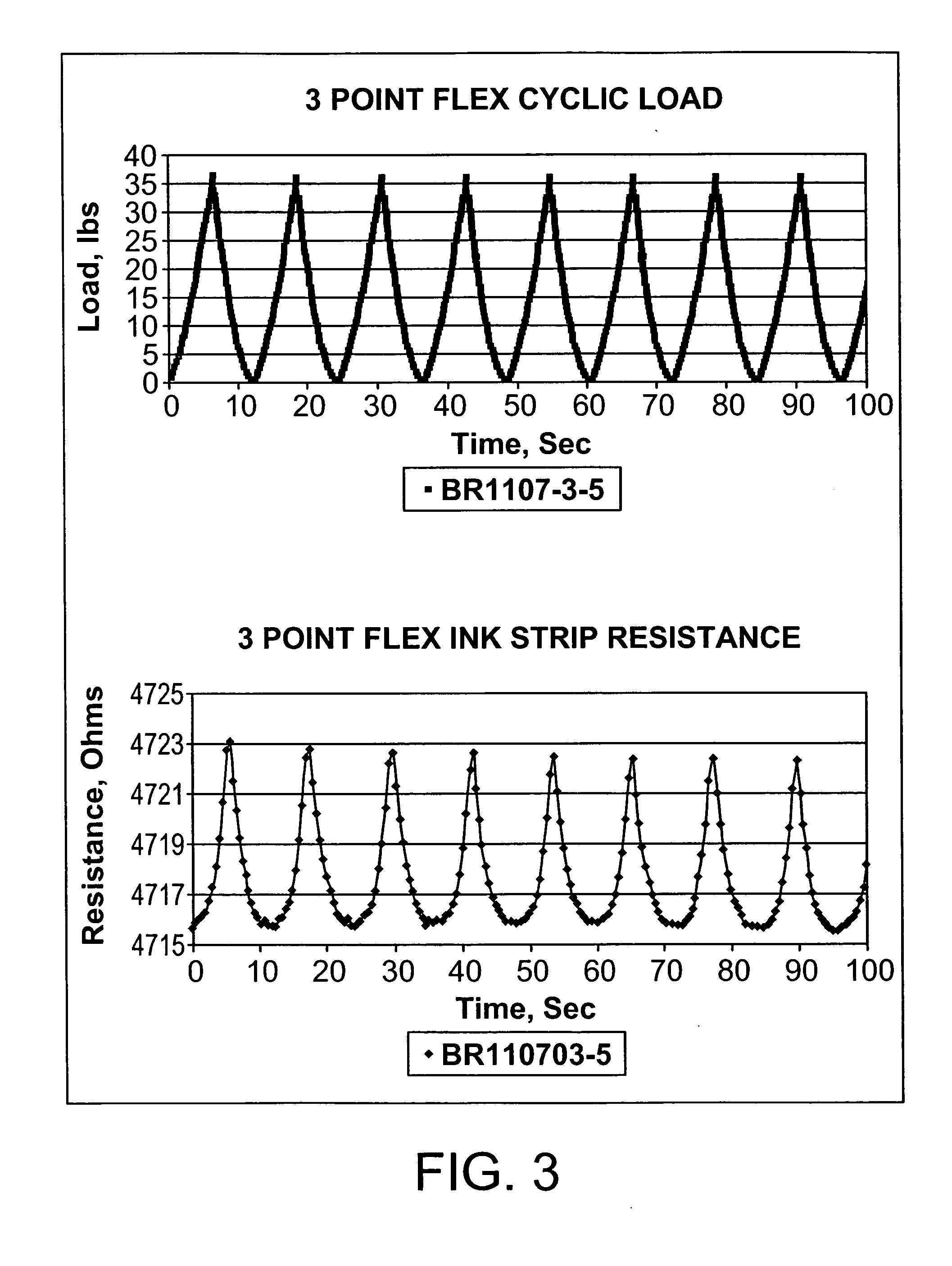
[0040] A 1″×6″ carbon fiber / epoxy composite laminate was subjected to a cyclical three point bend test in which the sample was loaded to 35 pounds then unloaded in a sinusoidal pattern. FIG. 3 illustrates the correlation between structural strain and changes in resistance. As can be seen, the sensor grid line resistance increases with applied load and returns to the initial resistance when the applied load is zero. With this small loading level, the resistance increases from an initial value of 4715 ohms to a value of 4723 ohms. Resistance levels rise to over 100 k-ohms when the sensor grid develops permanent cracks, so the sensing system is very sensitive over a wide range of strain values. It should be noted that after 100 cycles at approximately 2% strain, the sensor grid was still intact.

example 2

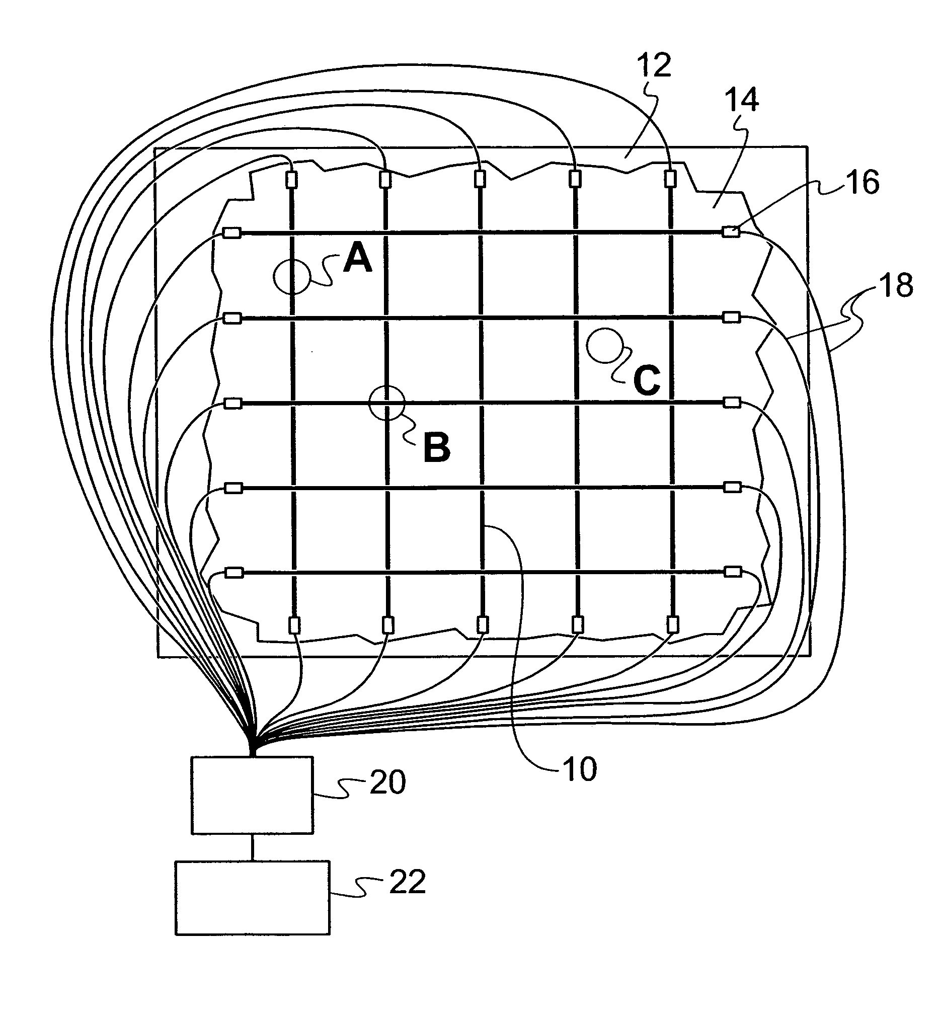
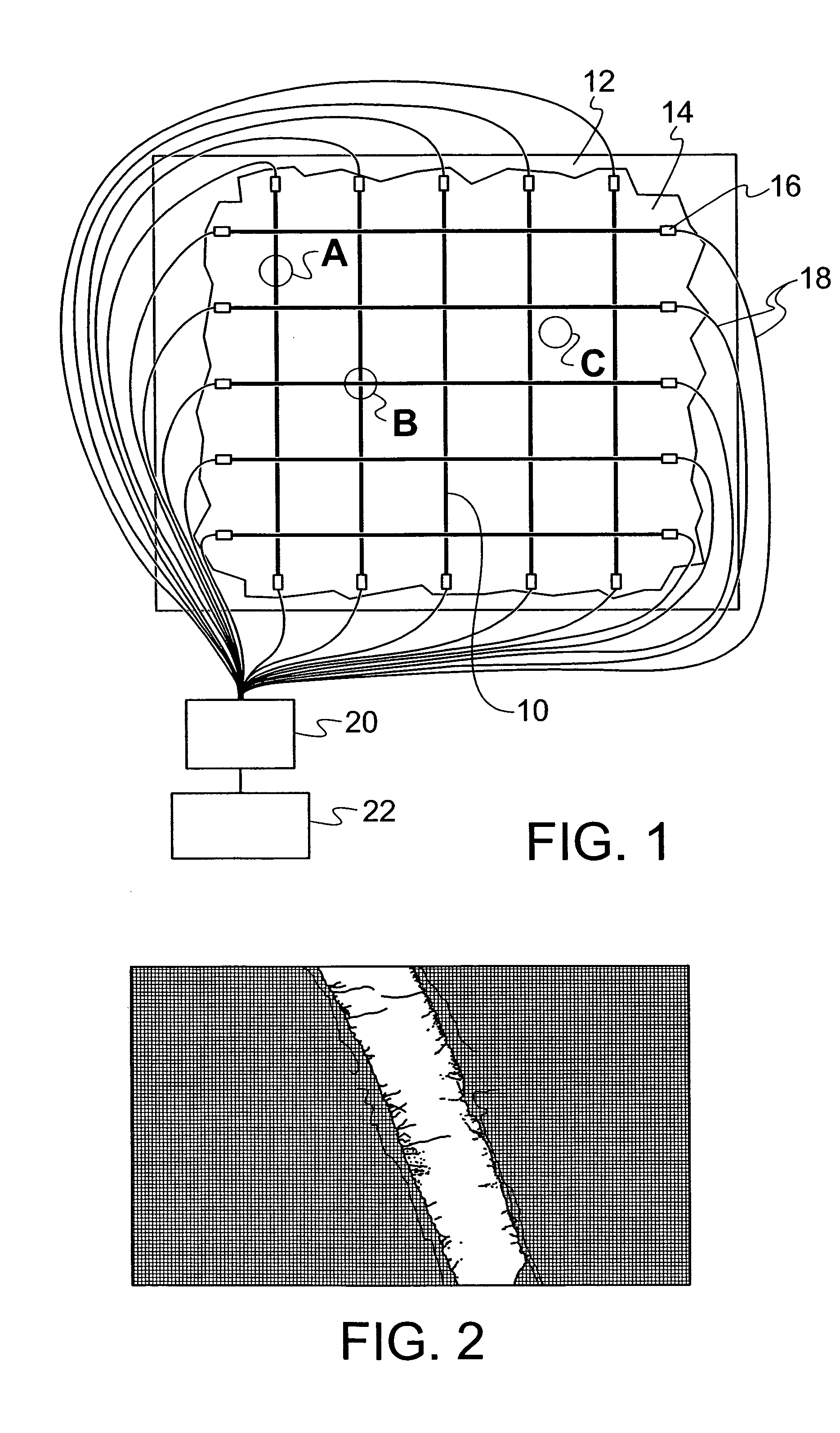
[0041] A 5″×5″ sensor grid was applied to a 12″×12″ carbon fiber / epoxy composite laminate. The grid lines had a spacing of two inches and were electrically isolated from each other. The laminate was supported with a ten inch diameter ring and a one inch diameter indentor was used to penetrate the laminate at the intersection of sensor lines X3 and Y3 as illustrated in FIG. 4. The circuits at X3 and Y3 were broken. Real-time data traces of indentor load and X-grid resistance values are shown in FIGS. 5A-5F. The load increases gradually as does the resistance value of X3. Resistance values of X2 and X4 also increase but at a reduced rate. Grid lines X1 and X5 which are supported almost entirely by the test ring show almost no change during the test. At 190 seconds there is an inflection in the load curve and X3 rapidly goes off scale. This is the time when the indentor tip pops through the plate. The loading continues and the indentor continues to punch through the plate as the load i...

example 3

[0042] A dynamic impact test was conducted on a 12″×12″ carbon fiber / epoxy / foam sandwich structure with a 5″×5″ sensor grid applied on its surface. A ⅞ inch diameter steel ball was shot with a velocity of 1000 feet / second at the sandwich panel which was supported by a circular ring. The ball was aimed at the intersection of sensor lines X3 and Y3 as depicted in FIG. 6. Resistance readings for all ten sensor lines were recorded at a frequency of 1 Mhz. The damage zone was limited to a diameter of approximately two inches. The carbon tow which makes up the braided structure of the sandwich skin still filled most of the damage zone, acting as tiny conductive brushes. It was noted that the sensor grid lines were still intact outside the damaged zone, which is an improvement over prior methods in which strain gages or other sensors fail when shock waves cause the sensor to pop off.

[0043]FIG. 7 shows the resistance reading of Y3 (impact site) and Y4 (nearest to impact). The resistance va...


PUM

PropertyMeasurementUnit
resistanceaaaaaaaaaa
diameteraaaaaaaaaa

Abstract

A sensing system for use in monitoring the structural health of a structure such as a polymeric matrix composite structure is provided. The system includes a sensor formed from a conductive ink containing carbon nanofibers and a polymeric resin, and a data acquisition system for acquiring and evaluating data from the sensor. The conductive ink may be applied directly to the structure to be monitored in the form of a grid pattern. Damage to the structure may be detected by measuring changes in resistance values detected from the sensor.

Description

CROSS REFERENCE TO RELATED APPLICATIONS [0001] This application claims the benefit of U.S. Provisional Application No. 60 / 583,239, entitled SENSOR FOR MONITORING THE STRUCTURAL HEALTH OF COMPOSITE STRUCTURES, filed Jun. 24, 2004. The entire contents of said application are hereby incorporated by reference.GOVERNMENT RIGHTS [0002] The government has rights in the invention pursuant to Contract No. 200-18-14W36063 awarded by GE Aircraft Engines / NASA Glenn.BACKGROUND OF THE INVENTION [0003] The present invention relates to a sensing system used to monitor the structural health of structures such as polymeric matrix composite structures, and more particularly, to a sensor which utilizes a conductive ink incorporating carbon nanofibers which may be applied to a structure. [0004] Monitoring the structural health of structures which are used over long periods of time has become increasingly important. Over time, structures such as architectural and vehicular structures as well as aircraft,...

Claims


Application Information

Patent Timeline
Patent Type & Authority Applications(United States)
IPC IPC(8): G01B7/16G01B11/16G01M5/00G01N27/20
CPCG01B7/18G01N27/205G01M5/0083G01M5/0033
Inventor RICE, BRIAN P.
Owner UNIV OF DAYTON
Why Eureka
Try Eureka