Transmit signal generator and method

a technology of transceiver and signal, applied in the direction of parametric amplifier, modulation, transmitter/receiver shaping network, etc., can solve the problems of affecting the reception of the signal by the receiver, affecting the efficiency of the receiver, and introducing modulation into the transmitted signal

a technology of transceiver and signal, applied in the direction of parametric amplifier, modulation, transmitter/receiver shaping network, etc., can solve the problems of affecting the reception of the signal by the receiver, affecting the efficiency of the receiver, and introducing modulation into the transmitted signal

US20050286652A1Active Publication Date: 2005-12-29SIGE SEMICON EURO

Image

  • Transmit signal generator and method
  • Transmit signal generator and method
  • Transmit signal generator and method

Examples


Embodiment Construction

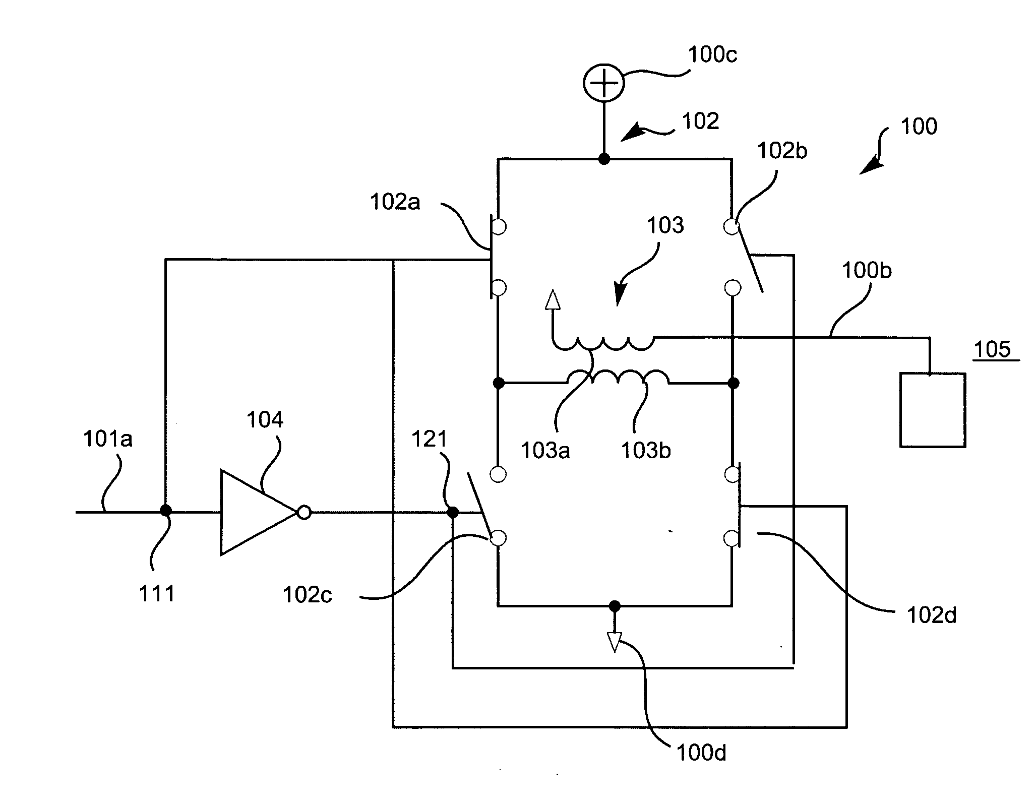
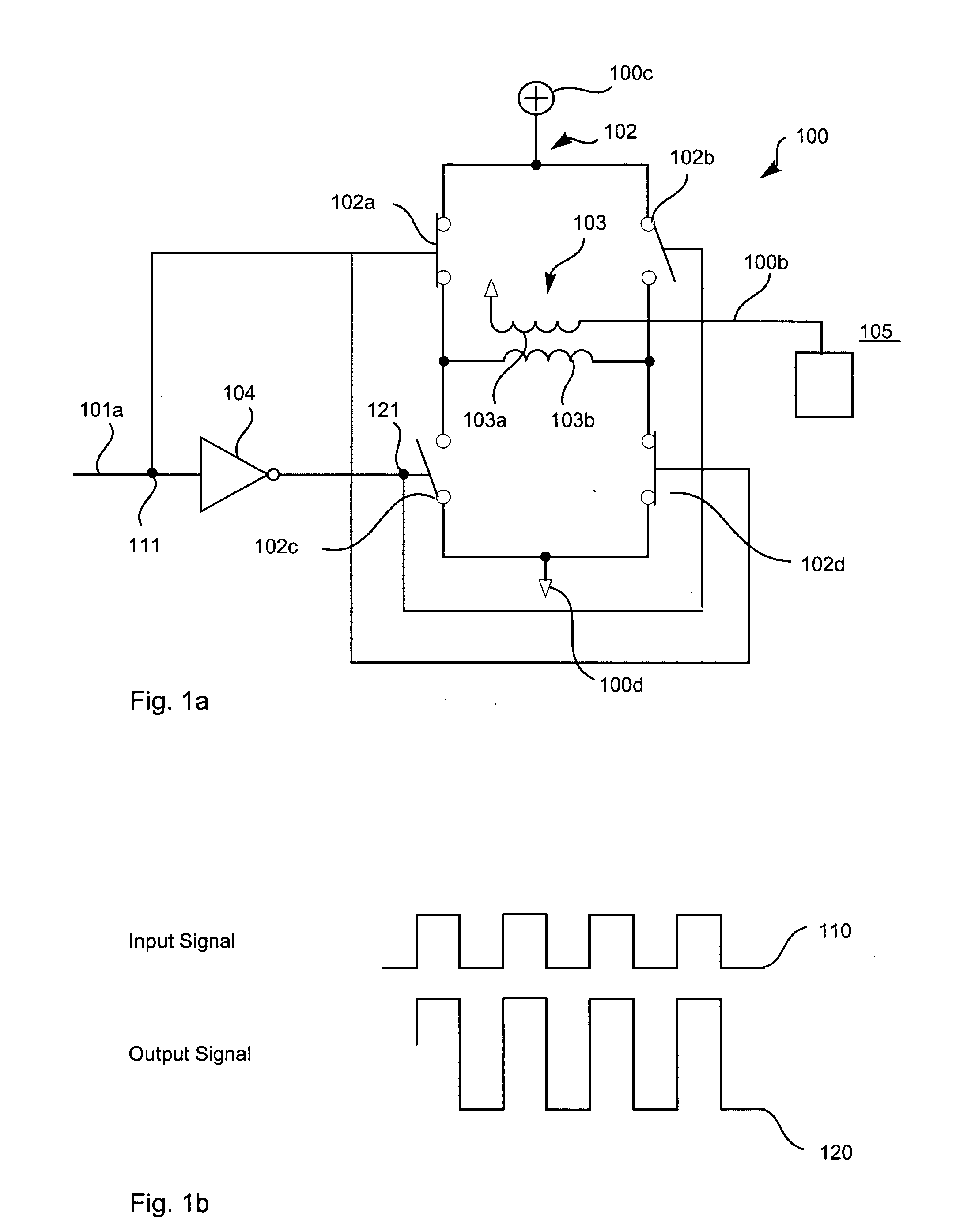
[0026]FIG. 1A illustrates a power amplifier (PA) output stage 100. The output stage 100 is primarily in the form of an H bridge 102 that is disposed between first and second supply voltage ports, 100c and 100d. The H bridge circuit 102 is primarily formed from two circuit branches. A first circuit branch has a first end thereof coupled with the first supply voltage port 100c, where a first side of a first high side switching circuit 102a is coupled thereto. Coupled to the second side of the first high side switching circuit 102a is a first end of a primary winding 103b of a transformer 103. Coupled to the second end of the primary winding 103b is a second low side switching circuit 102d, which is further coupled with the second supply voltage port 100d, terminating the first circuit branch. A second circuit branch has a first end thereof coupled with the first supply voltage port 100c, where a first side of a second high side switching circuit 102b is coupled thereto. Coupled to the...


PUM


Abstract

Disclosed is a method and apparatus for amplitude modulation of an RF transmit signal using pulse width modulation to control an amount of energy within each period. The apparatus includes a signal processing circuit with an input port for receiving of information indicative of a carrier frequency and modulation data. The signal processing circuit has a first output port and a second output port for providing of output signals having a phase relationship therebetween. A power amplifier is provided for receiving the output signals and for generating a pulse width modulated signal in dependence thereon.

Description

FIELD OF THE INVENTION [0001] The invention relates to the field of transmit signal generators and more specifically to the field of transmit signal generators for generating signal power levels that are comparable to those of existing power amplifiers for use in cellular telephone terminals and wireless LANs. BACKGROUND OF THE INVENTION [0002] One class of power amplifiers that perform with high efficiency are those that operate in a saturation mode. In many communication systems using frequency modulation (e.g. FSK), amplifiers are operated at or near their most efficient point of operation since minimal amplitude variation in the output signal occurs. Unfortunately, as demand grows for increased transmitted data bandwidth within each transmission channel, amplitude modulation is introduced into transmitted signals. With both frequency and amplitude modulation distortion becomes a more important figure of merit in respect of power amplifier performance. First, varying the signal p...

Claims


Application Information

Patent Timeline
29 Dec 2005
Publication
US20050286652A1
IPC
H03F1/06; H03F3/217; H03K5/00; H03K7/02; H03K11/00; H04B1/10; H04L25/49
CPC
H03F3/189; H03F3/217; H03F2200/324; H03K11/00; H03F2200/421; H03F2200/541; H03K7/02; H03F2200/351
Inventors
MACPHAIL, PHILIP; LORAINE, JEREMY