Organic electroluminescent device and method for producing the same

a luminescent device and electroluminescent technology, applied in the direction of discharge tube luminescnet screen, other domestic articles, natural mineral layered products, etc., can solve the problems of deterioration of luminescent brightness and durability of luminescent devices, difficulty in maintaining a constant layer thickness, and inferior improvement of production efficiency of dry method (vapor deposition method) for the production of thin film lamination, etc., to achieve high luminescent efficiency, high driving durability, and high brightness

Active Publication Date: 2005-12-29
UDC IRELAND
View PDF4 Cites 16 Cited by
  • Summary
  • Abstract
  • Description
  • Claims
  • Application Information

AI Technical Summary

Benefits of technology

[0007] The present invention provides an organic electroluminescent device that has high brightness (i.e., high luminescent efficiency) and high driving durability by employing a luminescent layer produced by a vapor-deposition method, and provides a method for producing the same.

Problems solved by technology

An organic electroluminescent device capable of emitting light with high brightness has been disclosed (for example, in Japanese Patent Application Laid-Open (JP-A) No. 2002-324679), which is produced by a wet method using a luminescent dopant having a relatively larger solubility in a solvent, because a dry method (vapor-deposition method) for the production of a thin film lamination is inferior in improvement of production efficiency due to the complexity of the production process.
Further, when forming a luminescent layer by the wet method, such problems exist as nonuniformity occuring in a layer due to evaporation of the solvent in a drying step after coating, and there is difficulty in maintaining a constant layer thickness.
There are also cases where impurities, oxygen and water contained in the solvent, the binder or the like adversely affect the luminescent layer to cause deterioration both of luminescent brightness and of the durability of the luminescent device.

Method used


Image

  • Organic electroluminescent device and method for producing the same
  • Organic electroluminescent device and method for producing the same
  • Organic electroluminescent device and method for producing the same

Examples


examples

[0103] The luminescent device of the invention will be described in more detail below with reference to the following examples, but the invention is not construed as being limited thereto.

example 7

[0118] A luminescent device of Example 7 was produced in the same manner as in Example 1 except that the hole transport layer was provided by the following wet method.

[0119] 6 mg of polyvinylcarbazole (PVK) having a weight average molecular weight of 1,100,000 in polystyrene conversion was dissolved in 1 mL of 1,2-dichloroethane to obtain a solution. The solution was coated on the hole injection layer (formed by vacuum deposition of copper phthalocyanine) by a spin coating method at a rotation rate of 1,000 rpm for 1 second to form a hole transport layer having a thickness of 0.05 μm, and further thereon, a luminescent material Ir-1 and a host material were co-vapor-deposited to form a luminescent layer.

[0120] The resultant luminescent device was evaluated for green luminescent capability in the same manner as in Example 1. The results thus obtained are shown in Table 1.


PUM

PropertyMeasurementUnit
work functionaaaaaaaaaa
thicknessaaaaaaaaaa
thicknessaaaaaaaaaa

Abstract

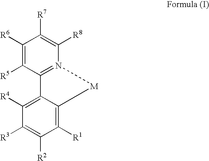
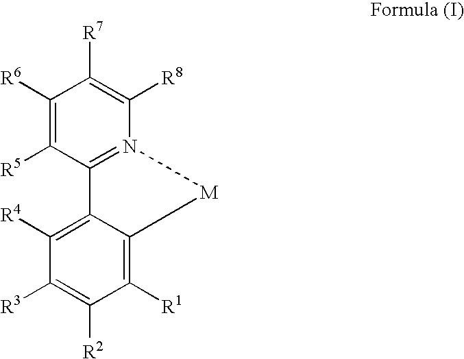
An organic electroluminescent device and a method for producing the same, the organic electroluminescent device including a luminescent layer produced by a vapor-deposition method disposed between a pair of electrodes, the luminescent layer containing at least one host material and at least one metal complex including a partial structure represented by formula (I): wherein M represents a metal atom, R1, R2 and R4 to R8 each independently represent a hydrogen atom or a substituent, and R3 represents a group represented by formula (II), an alkoxy group or an aryloxy group: wherein R11 to R13 each independently represent a hydrogen atom or a substituent, provided that at least two of them each independently represent an alkyl group or an aryl group.

Description

CROSS-REFERENCE TO RELATED APPLICATION [0001] This application claims priority under 35 USC 119 from Japanese Patent Application No. 2004-189857, the disclosure of which is incorporated by reference herein. BACKGROUND OF THE INVENTION [0002] 1. Field of the Invention [0003] The present invention relates to a luminescent device that emits light by converting electric energy to light. The luminescent device of the invention can, in particular, be suitably used as an organic electroluminescent (EL) device. [0004] 2. Description of the Related Art [0005] Organic electroluminescent (EL) devices are attracting attention as promising display devices because they provide luminescence with high brightness at a low voltage. An organic electroluminescent device capable of emitting light with high brightness has been disclosed (for example, in Japanese Patent Application Laid-Open (JP-A) No. 2002-324679), which is produced by a wet method using a luminescent dopant having a relatively larger so...

Claims


Application Information

Patent Timeline
Patent Type & Authority Applications(United States)
IPC IPC(8): C09K11/06H01L51/00H01L51/50H05B33/14
CPCC09K11/06C09K2211/1029C09K2211/185H01L51/006H05B33/14H01L51/0071H01L51/0085H01L51/5012H01L51/007Y10S428/917H10K85/6565H10K85/633H10K85/657H10K85/342H10K50/11
Inventor NAKAMURA, TETSUOIGARASHI, TATSUYAMURAKAMI, TAKESHIMISHIMA, MASAYUKI
Owner UDC IRELAND
Why Eureka
Try Eureka