Direct write and freeform fabrication apparatus and method

a technology of freeform fabrication and writing apparatus, which is applied in the direction of additive manufacturing process, additive manufacturing with liquids, instruments, etc., can solve the problems of inapplicability of inkjet technology, many other techniques are limited to the production of parts, and most prior-art layer manufacturing techniques are only applicable to parts. , to achieve the effect of improving the accuracy of parts

Inactive Publication Date: 2005-12-29
NORTH DAKOTA STATE UNIVERSITY
View PDF7 Cites 201 Cited by
  • Summary
  • Abstract
  • Description
  • Claims
  • Application Information

AI Technical Summary

Benefits of technology

[0039] If the directed energy source comprises a laser beam, it can also be used to remove a portion of a substrate (e.g., to create a via hole in a printed circuit board) for direct write manufacturing of electronic components, or to trim the edge of a deposited layer in a layer manufacturing process for improved part accuracy.
[0040] Another embodiment of the apparatus can be generally described as a method of freeform fabrication of three-dimensional objects and direct writing of devices using spatially tailored material compositions, comprising: (a) creating an image of the device or object on a computer, the image including a plurality of segments or data points defining the object, each of the segments or data points being coded with a specific material composition; (b) evaluating the data files representing the device or object to locate any un-supported feature of the device or object, followed by defining a support structure for the un-supported feature and creating a plurality of segments or data points defining the support structure; (c) generating program signals corresponding to each of the segments or data points for both the device or object and the support structure in a predetermined sequence; (d) dispensing and depositing droplets of liquid compositions and solid powder particles of predetermined material compositions at predetermined proportions onto a target surface of an object-supporting platform and operating a directed energy beam to induce a chemical change or physical transition to the deposited liquid compositions, or powder particles, or both, for forming the device or object and the support structure; and (e) moving the deposition sub-system and the object-supporting platform, during the deposition step, in response to the programmed signals relative to one another in a plane defined by first and second directions and in a third direction orthogonal to the plane in a predetermined sequence of movements such that the material compositions are deposited in free space as a plurality of segments or beads sequentially formed so that the last deposited segment or bead overlies at least a portion of the preceding segment or bead in contact therewith to form the support structure and the multi-material three-dimensional device or object. In addition a directed energy source, such as a laser beam, can be utilized to remove a portion of the deposited liquid composition, or the deposited solid powder, or both, or to remove a portion of a reaction product between the dispensed liquid composition and the dispensed powder particles.
[0041] Numerous beneficial aspects are described for the apparatus and methods according to the present invention. These aspects can be implemented singly or in various combination without departing from the teachings of the present invention. No single one of these aspects or combination is solely responsible for the desirable attributes provided according to the invention.
[0042] An aspect of the invention is a 3-D freeform fabrication and direct write apparatus and method controlled by a computer in which a variety of materials can be processed and a built-up in a point-by-point and layer-by-layer manner. Another aspect of the invention is the use of a directed energy source which aside from changing the state of materials being built up can be utilized for changing the built up items according to a subtractive mechanism (sculpting).
[0043] Another aspect of the invention is the performing of direct write manufacturing (DWM) for fabricating electronic devices and MEMS devices.
[0044] Another aspect of the invention provides for building up 3-D objects while varying the material composition dynamically as it is being built.

Problems solved by technology

Unfortunately, inkjet technology is only applicable to dispensing liquids in a limited viscosity range, which leaves out a majority of preferred materials for performing 3-D fabrication, such as solid powders with high melting points.
Most of the prior-art layer manufacturing techniques have been substantially limited to the production of parts from homogeneous material compositions.
Furthermore, due to the specific solidification mechanisms employed, many other techniques are limited to the production of parts from specific polymers.
This is an interesting SFF process that is specifically designed for the purposes of rapid prototyping and rapid tooling of highly accurate 3-D objects, but does not facilitate the direct-writing of microelectronic components.
Indeed, most of the prior-art techniques are not directly applicable for direct write manufacturing of microelectronic or MEMS devices.
It should be noted that, although direct writing may also be accomplished in the sub-micron range using electron beams or focused ion beams, these techniques are not appropriate for large scale rapid prototyping due to their small scale and, hence, low deposition rates.
Due to the film material being vaporized by the action of the laser, LIFT is inherently a homogeneous, pyrolytic technique and typically cannot be used to deposit complex crystalline or multi-component materials.
Furthermore, because the material to be transferred is vaporized, it becomes more reactive and can more easily become degraded, oxidized or contaminated.
The method is not well suited for the transfer of organic materials, since many organic materials are fragile and thermally labile and can be irreversibly damaged during deposition.
Other shortcomings of the LIFT technique include poor uniformity, morphology, adhesion, and resolution.
Further, in response to the high peak temperatures involved in the process, there is a danger of ablation or sputtering of the support, which can cause the incorporation of impurities in the material that is deposited on the receiving substrate.
For some intended transfer materials, it may be difficult to find a suitable matrix material that is physically and chemically compatible with the transfer material so that the “lifting” procedure can be properly carried out.
In general, DWM techniques are not suitable for use as solid freeform techniques for a number of reasons, including but not limited to the following.
Other techniques, such as LIFT and MAPLE, do not allow for deposition of a support structure in a layer-wise 3-D part-building process.
The commercially available systems for carrying out these techniques are not typically configured with a thickness-direction positional device and control.

Method used


Image

  • Direct write and freeform fabrication apparatus and method
  • Direct write and freeform fabrication apparatus and method
  • Direct write and freeform fabrication apparatus and method

Examples


Embodiment Construction

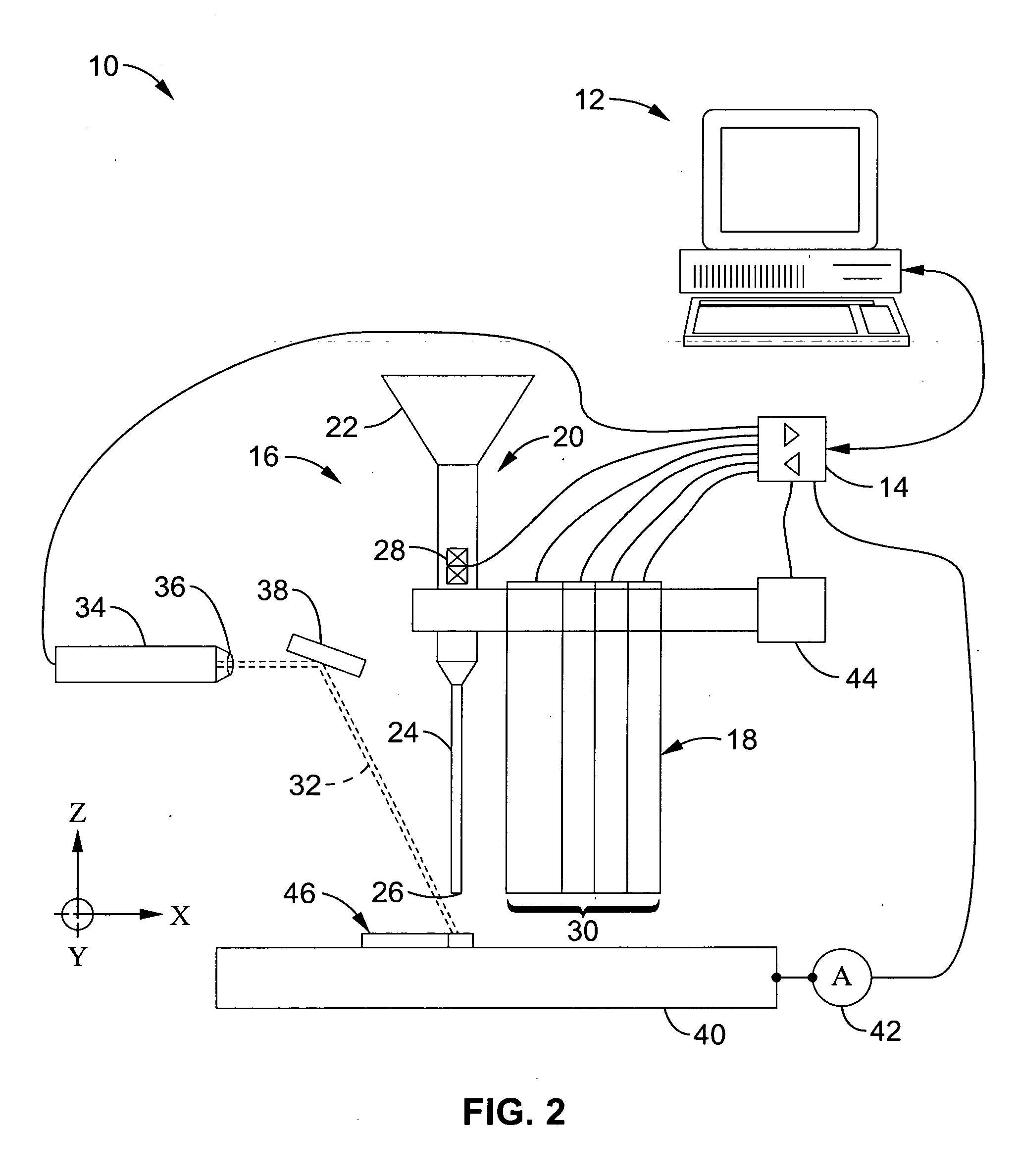
[0059] Referring more specifically to the drawings, for illustrative purposes the present invention is embodied in the apparatus generally shown in FIG. 2 through FIG. 3B. It will be appreciated that the apparatus may vary as to configuration and as to details of the parts, and that the method may vary as to the specific steps and sequence, without departing from the basic concepts as disclosed herein.

[0060]FIG. 2 illustrates by way of example one embodiment 10 of the direct-writing and freeform 3-D build up apparatus. This apparatus is equipped with a computer 12 for creating a drawing or image (i.e. CAD system) of a device or an object and, through a hardware controller 14 (data acquisition and control head) that monitors and controls the operation of other components of apparatus 10. Hardware controller 14 preferably comprises necessary inputs and outputs for monitoring the process and outputting proper control signals, such as for example comprising a signal generator, amplifie...


PUM

PropertyMeasurementUnit
droplet sizesaaaaaaaaaa

Abstract

A direct write or freeform fabrication apparatus and process for making a device or a three-dimensional object. By way of example the method comprises: (a) providing a target surface on an object-supporting platform; (b) operating a material deposition sub-system comprising a liquid deposition device for dispensing at least a liquid composition and a solid powder-dispensing device for dispensing solid powder particles to selected locations on the target surface; (c) operating a directed energy source for supplying energy to the dispensed liquid composition and the dispensed powder particles to induce a chemical reaction or physical transition thereof at the selected locations; and (d) moving the deposition sub-system and the object-supporting platform relative to one another in a plane defined by first and second directions to form the dispensed liquid composition and the dispensed powder particles into the device or object. An apparatus is also provided for carrying out this process.

Description

CROSS-REFERENCE TO RELATED APPLICATIONS [0001] This application claims priority from, and is a 35 U.S.C. § 111 (a) continuation of, co-pending PCT international application number PCT / US2004 / 033964, filed Oct. 13, 2004, incorporated herein by reference in its entirety, which claims priority from U.S. provisional application Ser. No. 60 / 511,517, filed on Oct. 14, 2003, incorporated herein by reference in its entirety.STATEMENT REGARDING FEDERALLY SPONSORED RESEARCH OR DEVELOPMENT [0002] This invention was made with Government support under Grant No. DMEA90-02-C-0224, awarded by the Department of Defense. The Government has certain rights in this invention.INCORPORATION-BY-REFERENCE OF MATERIAL SUBMITTED ON A COMPACT DISC [0003] Not Applicable NOTICE OF MATERIAL SUBJECT TO COPYRIGHT PROTECTION [0004] A portion of the material in this patent document is subject to copyright protection under the copyright laws of the United States and of other countries. The owner of the copyright right...

Claims


Application Information

Patent Timeline
Patent Type & Authority Applications(United States)
IPC IPC(8): B29C67/00G06F19/00
CPCB22F3/1055B22F2998/00B28B1/00B28B1/001B29C67/0055B22F2003/1057B29C67/0077B29L2031/3061B29C67/0059B22F3/003B29C64/106B29C64/112B29C64/153Y02P10/25B22F10/30B22F10/14B22F12/30B22F10/80B22F12/44B22F10/43B22F12/52B22F12/53B22F12/55B22F12/90B22F12/41B22F12/57
Inventor YANG, LAIXIAAAGAAH, MOHAMMAD RASTGAARMAHINFALAH, MOHAMMADJANG, BOR Z.GRIER, DEAN G.
Owner NORTH DAKOTA STATE UNIVERSITY
Why Eureka
Try Eureka