Separation apparatus and separation method

a separation apparatus and separation method technology, applied in separation processes, laboratory glassware, instruments, etc., can solve the problems of generating irreversible denaturalization or deactivation or the like of the target substance, deteriorating separation efficiency, and not always suitable design for affinity chromatography that involves filling the column, etc., to achieve higher efficiency, higher activity, and high efficiency

Inactive Publication Date: 2006-01-05
NEC CORP
View PDF9 Cites 185 Cited by
  • Summary
  • Abstract
  • Description
  • Claims
  • Application Information

AI Technical Summary

Benefits of technology

[0027] As have been described above, according to the present invention, by comprising a channel provided in a substrate, a separating portion provided in the channel and a fine channel provided in the separating portion and having a width that is smaller than that of the channel, and by forming in the separating portion a layer of an adsorptive substance selectively adsorbing or binding to the specific substance, the separation apparatus or the method for separating the specific substance in the sample with higher efficiency utilizing a specific interaction can be achieved. In addit

Problems solved by technology

However, the affinity chromatography that involves filling the column is not always suitable in terms of a design for efficiently separating a very small amount of a sample.
However, in such configuration, similarly as in the case of the affinity chromatography utilizing the conventional column, when the filling rate of the affinity adsorbent is higher the affinity adsorbents can not be arranged with sufficient intervals therebetween, and, in turn, the entire surface of the affinity adsorbent cannot be involved in the adsorption with the target substance, thereby causing a problem of deteriorating th

Method used


Image

  • Separation apparatus and separation method
  • Separation apparatus and separation method
  • Separation apparatus and separation method

Examples


first embodiment

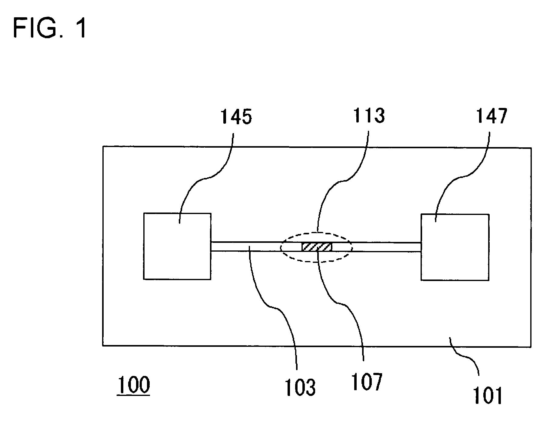
[0052]FIG. 1 is a top view of a separation apparatus 100 according to the present embodiment. In separation apparatus 100, a channel 103 is provided on a substrate 101, and a separating region 113 including a separating portion 107 is formed in a part of the channel 103. Further, both ends of the channel 103 are communicated with a sample introduction portion 145 and a fluid reservoir 147, respectively.

[0053] Here, an upper surface of the channel 103 may be coated with a coating member. Drying of a liquid sample is suppressed by providing the coating member on the upper surface of the channel 103. Moreover, when a component in the sample includes a substance having a higher-order structure such as a protein, irreversible denaturation of the component in the gas-liquid interface is suppressed by tightly sealing the inside of the channel 103 by using a coating member having a hydrophilic surface.

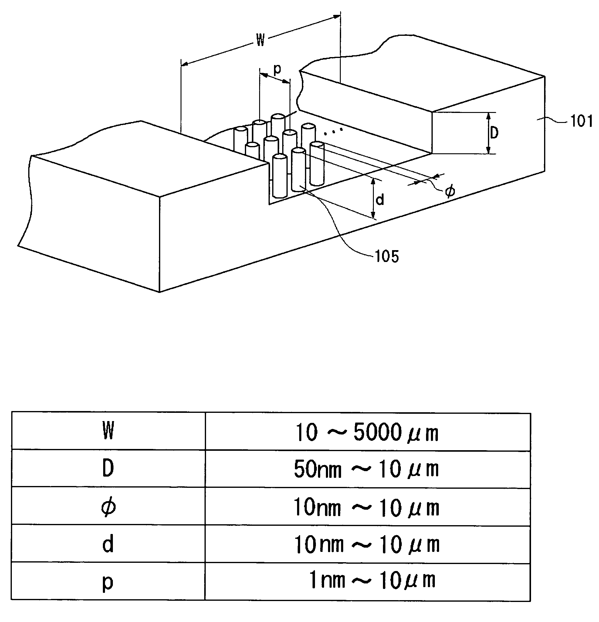
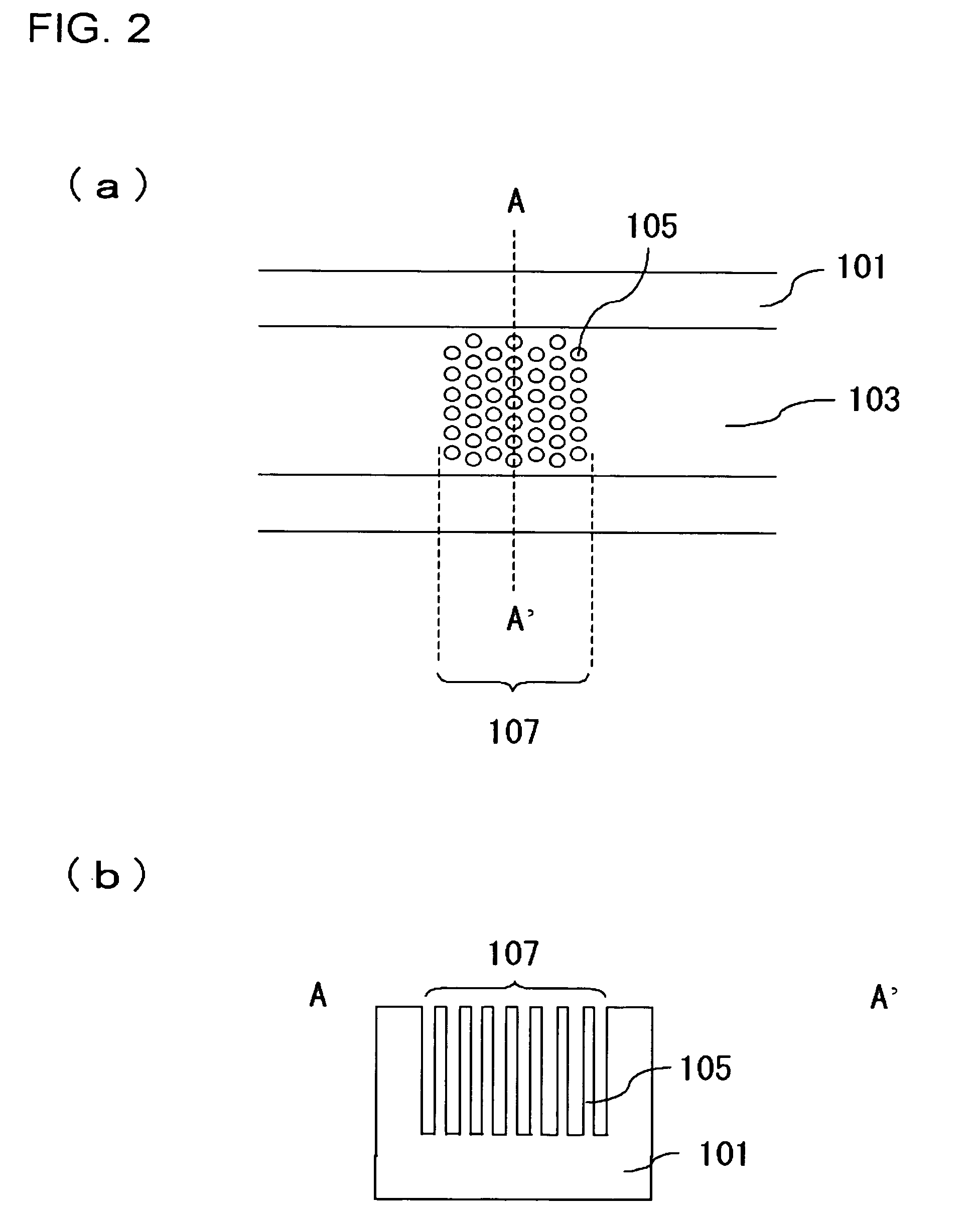
[0054]FIG. 2 is an enlarged view of the separation region 113 in the separation apparatu...

second embodiment

[0109] The present embodiment has a configuration, in which the separating portion 107 in the separation apparatus of the first embodiment includes a plurality of fragmentalized channels separated with partition walls. FIG. 9 is a drawing illustrating a configuration of the separating region 113 of the separation apparatus 100 according to the present embodiment. FIG. 9(a) shows a top view, and FIG. 9(b) is a cross-sectional view along C-C direction shown in FIG. 9(a). In the separating portion 153, partition walls 151 are regularly formed at equal intervals in the channel 103, and the liquid flows through the gaps between the partition walls 151. More specifically, the channels having narrower widths than the channel 103 are formed, and thus these fine channels become channels 149 for the separation. Since the adsorptive substance layer 109 is formed on the surface of the channels 149 for the separation similarly as in the first embodiment, the specific substance A′ in the sample l...

third embodiment

[0111] The present embodiment has a configuration, in which electrodes are provided in the interior of the pillar 105 provided in the separating portion 107 in the separation apparatus 100 described in the first embodiment, and an electric potential is applied to the electrodes. An example of a method for forming electrodes inside of the separating portion 107 will be described as follows. FIG. 14 is a process cross-sectional view, illustrating a method for manufacturing a separation apparatus according to the present embodiment. At first, a metal mold 173 having portions for mounting electrodes is prepared (FIG. 14(a)). Then, electrodes 175 are installed into the metal mold 173 (FIG. 14(b)). Material employed for the electrode 175 may be Au, Pt, Ag, Al, Cu or the like, for example. Then, a metal mold 179 for coating is set on the metal mold 173 to fix the electrodes 175, and resin 177 for forming a substrate 101 is injected into the metal mold 173 to conduct a molding (FIG. 14(c))....


PUM

PropertyMeasurementUnit
Sizeaaaaaaaaaa
Electric potential / voltageaaaaaaaaaa
Widthaaaaaaaaaa

Abstract

A channel (103) is formed in a substrate (101), and a portion of the channel (103) is provided with a separating portion (107). A number of pillars are formed in the separating portion (107), and an adsorptive substance layer having an adsorptive substance, which exhibits a specific interaction for a specific substance, immobilized on the surface thereof, is formed. Once a sample is introduced into the channel (103), the specific substance is adsorbed on the adsorptive substance layer to be separated from other components. After washing the inside of the channel (103) with a buffer solution, the specific substance is desorbed from the adsorptive substance layer by flowing a eluting solution through the channel (103) and the specific substance is recovered.

Description

BACKGROUND OF THE INVENTION [0001] 1. Field of the Invention [0002] The present invention relates to a separation apparatus, a separation method and a mass spectrometry system, and more particularly relates to a separation apparatus that utilizes specific interactions between substances. [0003] 2. Related Art of the Invention [0004] Affinity chromatography is a chromatography, in which a substance having specific interaction with a substance to be separated and purified is immobilized onto insoluble carriers to produce affinity adsorbents, and the resultant affinity adsorbents are charged into a column, and a target substance in a sample solution is adsorbed on the affinity adsorbent, thereby being separated. The affinity chromatography is a method of separating a component by utilizing the specific interaction between substances and particularly useful for separating and purifying a bio-derived material. [0005] However, the affinity chromatography that involves filling the column i...

Claims


Application Information

Patent Timeline
IPC IPC(8): B01D15/08B01D69/00B01D69/14B01D71/02B01J20/34B01L3/00G01N1/34
CPCB01D67/0062B01D69/00B01D69/141B01D71/027B01L3/502707G01N1/405B01L3/502753B01L2200/0631B01L2300/0816G01N1/34B01L3/502746
Inventor SANO, TORUBABA, MASAKAZUIIDA, KAZUHIROKAWAURA, HISAIGUCHI, NORIYUKISOMEYA, HIROKOASOGAWA, MINORU
Owner NEC CORP
Why Eureka
Try Eureka