High current inductor and the manufacturing method

a high current inductor and manufacturing method technology, applied in the direction of inductances, inductances with magnetic cores, encapsulation/impregnation, etc., can solve the problems of affecting the manufacturing the inductance efficiency is greatly diminished, and the actual efficiency of the inductor is badly affected. to achieve the effect of improving the dcr performance of the inductor

Inactive Publication Date: 2006-01-05
CHENG CHANG MAO
View PDF5 Cites 42 Cited by
  • Summary
  • Abstract
  • Description
  • Claims
  • Application Information

AI Technical Summary

Benefits of technology

[0006] The main purpose of the present Invention is to provide a kind of inductor with the characteristic of resisting high current, and with the structure of magnet envelope tightly wrapping the periphery of the conductor coil, the inductor can not only meet the requirements to accept higher current, but also achieve better saturation characteristic.
[0009] The additional purpose of the invention is to provide a kind of inductor with the characteristic of resisting high current, with the structure of magnet envelope totally wrapping the conductor coil, so that gain an inductor in which the magnet envelope can easily form a tightly wrapping structure through die-casting.
[0010] The ultimate purpose of the invention is to provide a kind of inductor with the characteristic of resisting high current, with the structure of magnet envelope totally wrapping the conductor coil, which can replace the traditional E-shape or toroid coil inductor, and because the inductor have the advantage that use the conductor coil with less turns to meet the requirements for same inductance, so that can greatly improve the DCR performance of the inductor.

Problems solved by technology

Although the conductor coil of the common inductor can be fixed inside the chamber of the frame through stuffings or emissions, because the conductor coil is not directly integrated with the frame, so the efficiency achieved by the inductor is greatly diminished.
But, because the supporting parts must be dismantled and the second injection moulding must be carried out with the magnet molding material, so other than it will badly affect the manufacturing efficiency of the inductor, it there is any deviation of the positioning the conductor coil, the actual efficiency of the inductor will be badly affected too.
However, because the production process involves paste injection and press mould of the thin paste magnet ceramic material, so other than badly affecting the manufacturing efficiency, Many uncertainties in the molding operation of mixing thin paste with conductor coil also affect the efficiency of the inductor.

Method used


Image

  • High current inductor and the manufacturing method
  • High current inductor and the manufacturing method
  • High current inductor and the manufacturing method

Examples


Embodiment Construction

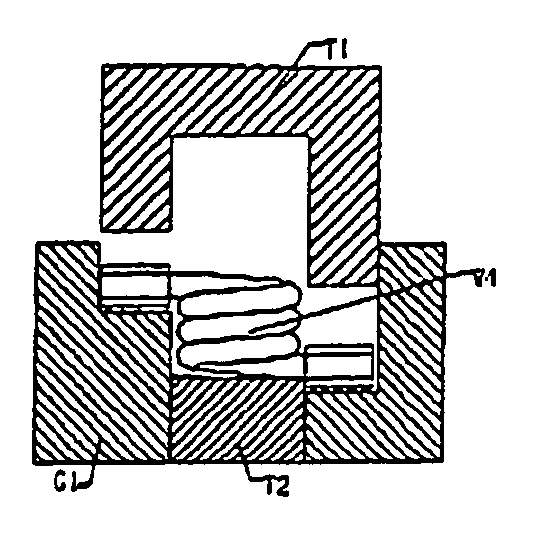
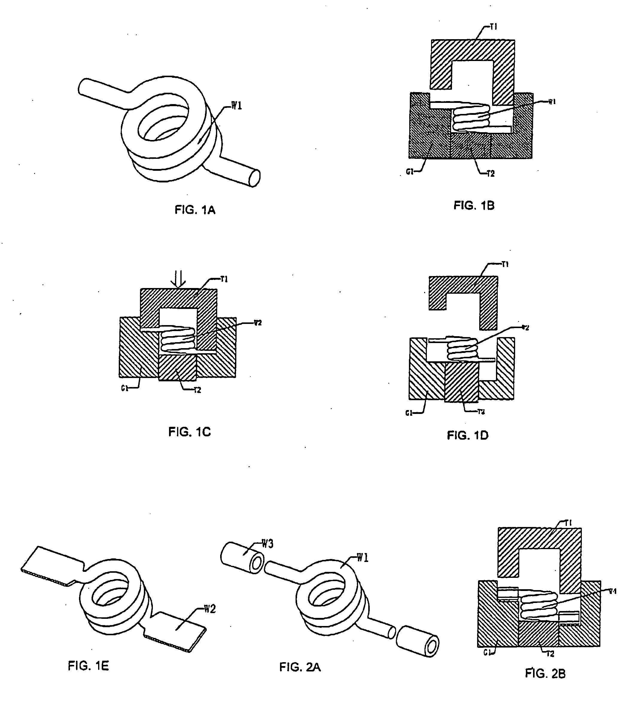
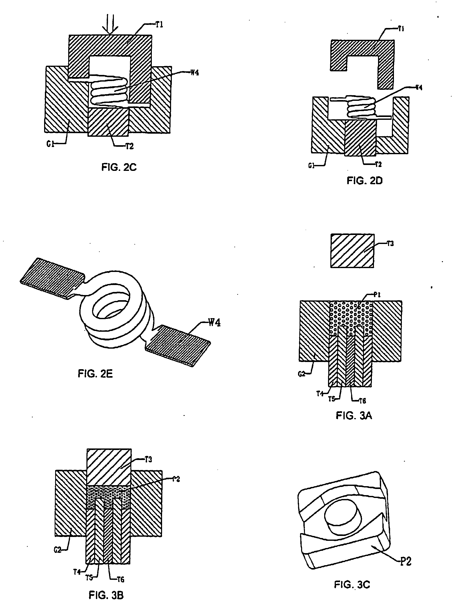
[0023] The inductor disclosed in the invention consists of a conductor coil and a magnet envelope which tightly wraps the periphery of the coil and form the main body of the inductor. In addition, the two extending parts of the conductor coil extend to outside of the magnet envelope to form terminal electrode.

[0024] The magnet envelope mainly consists of materials including three types of metal magnet powder (A magnet powder, B magnet powder and C magnet powder) plus insulation material (Polyester resin) X, Epoxy, Silicone and lubricant (Zinc Stearate), of which all of the three types of metal magnet powder mainly consist of carbonyl iron powder, and the difference is that the granule size of A magnet powder is 8 μm, and that of B magnet powder is 6 μm and C magnet powder is 4 μm.

[0025] Since the granule size of the three types of metal magnet powder are different, in principle, if the granules are larger, AL value is higher, core loss is larger and the application frequency is lo...


PUM

PropertyMeasurementUnit
granule sizeaaaaaaaaaa

Abstract

An inductor with the characteristic of resisting high current comprising a conductor coil and a magnet envelope, the magnet envelope tightly wraps the periphery of the conductor coil and forms the main body of the inductor, and the two extending parts of the conductor coil extend to outside of the main body of the inductor, forming terminal electrode. As of the manufacturing method, it includes the part of toroid coil and the extending parts composing the conductor coil. After the toroid coil part is winded into rings, the unwinded wire ends form the extending parts. Through magnet envelope die-casting and wrapping the molded magnet core of the conductor coil to form the main body of the inductor, and the extending parts of the conductor coil extend to outside of the main body to form the terminal electrode.

Description

FIELD OF THE INVENTION [0001] The present invention relates to an inductor with the characteristic of resisting high current, and more particularly, to an inductor with a kind of magnet envelope tightly wrapping the periphery of the toroid coil of the conductor coil which enables the characteristic to resist high current. While the way to make the inductor is a kind of original method suitable for making surface mount design (SMD) inductor as well as plug-in inductor. BACKGROUND OF THE INVENTION [0002] In general, according to the manufacturing method to make common inductors, a frame with open side chamber should be made at first in which a conductor coil mounted with magnet core is mounted inside the chamber, the coil can move freely, finally stuffings or emissions are used to fix the conductor coil inside the chamber and the two conducting wire terminals are bended and covered outside the frame to form a inductor structure. [0003] Although the conductor coil of the common inducto...

Claims


Application Information

Patent Timeline
Patent Type & Authority Applications(United States)
IPC IPC(8): H01F27/02H01F17/00H01F17/04H01F27/255H01F27/29H01F37/00H01F41/00H01F41/02H01F41/10
CPCH01F27/255H01F27/292H01F41/005Y10T29/4902H01F41/10H01F2017/046H01F2017/048H01F41/0246
Inventor CHENG, CHANG MAO
Owner CHENG CHANG MAO
Why Eureka
Try Eureka