
Method for manufacturing microlens and apparatus for manufacturing the same

Inactive Publication Date: 2006-01-19
SEIKO EPSON CORP
View PDF6 Cites 33 Cited by
  • Summary
  • Abstract
  • Description
  • Claims
  • Application Information

AI Technical Summary

Benefits of technology

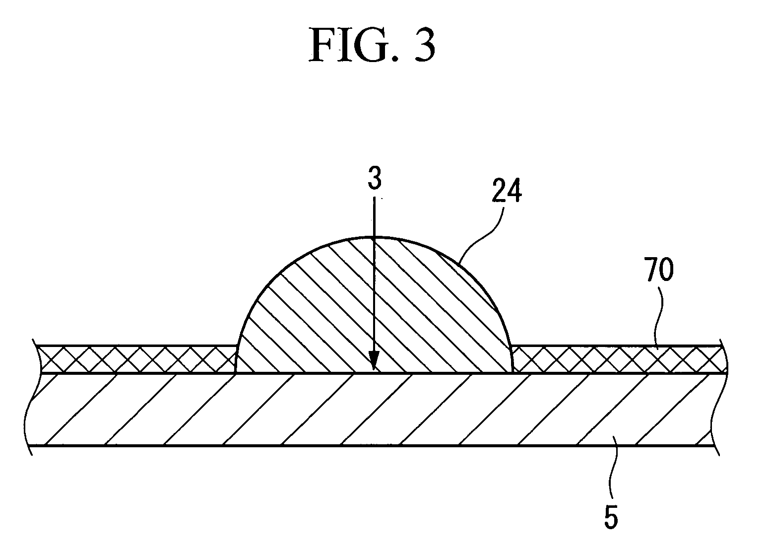
[0012] With this method, even if the liquid material before ejection has a low viscosity, the viscosity thereof can be increased significantly by irradiating the liquid drops after ejected with ultraviolet light. Thus, wetting and spreading of the liquid drop after it is made to land on the substrate is limited, thereby making formation of small-diameter microlenses possible. In addition, since control of the surface energy of the substrate is not required, a close adhesion between the microlenses and the substrate is ensured.
[0014] When an ultraviolet curing resin material is used as the material of the microlenses, the viscosity thereof can be increased significantly by irradiating the liquid drops after ejected with ultraviolet light. In particular, the curing rate of epoxy resins by radiation with ultraviolet light is relatively high since epoxy resins cure by cationic polymerization. Thus, the viscosity thereof can be increased significantly by irradiating the liquid drops after ejected with ultraviolet light. In addition, curing shrinkage and the coefficients of linear expansion of epoxy resins are relatively small. Therefore, epoxy resins enable precise formation of microlenses when they are used as an ultraviolet curing resin material.

Problems solved by technology

Thus, wetting and spreading of the liquid drop after it is made to land on the substrate is limited, thereby making formation of small-diameter microlenses possible.

Method used


Image

  • Method for manufacturing microlens and apparatus for manufacturing the same
  • Method for manufacturing microlens and apparatus for manufacturing the same
  • Method for manufacturing microlens and apparatus for manufacturing the same

Examples


Embodiment Construction

[0024] Hereafter, various embodiments of the present invention will be described with reference to the drawings. In addition, in respective drawings used for the following description, the scale is changed for each member so that each member is of a size which can be depicted in the drawing.

Method for Manufacturing Microlens

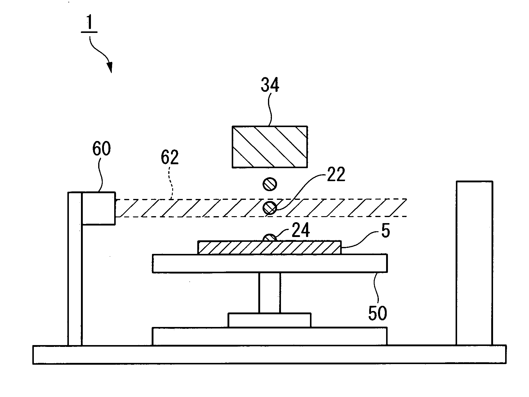
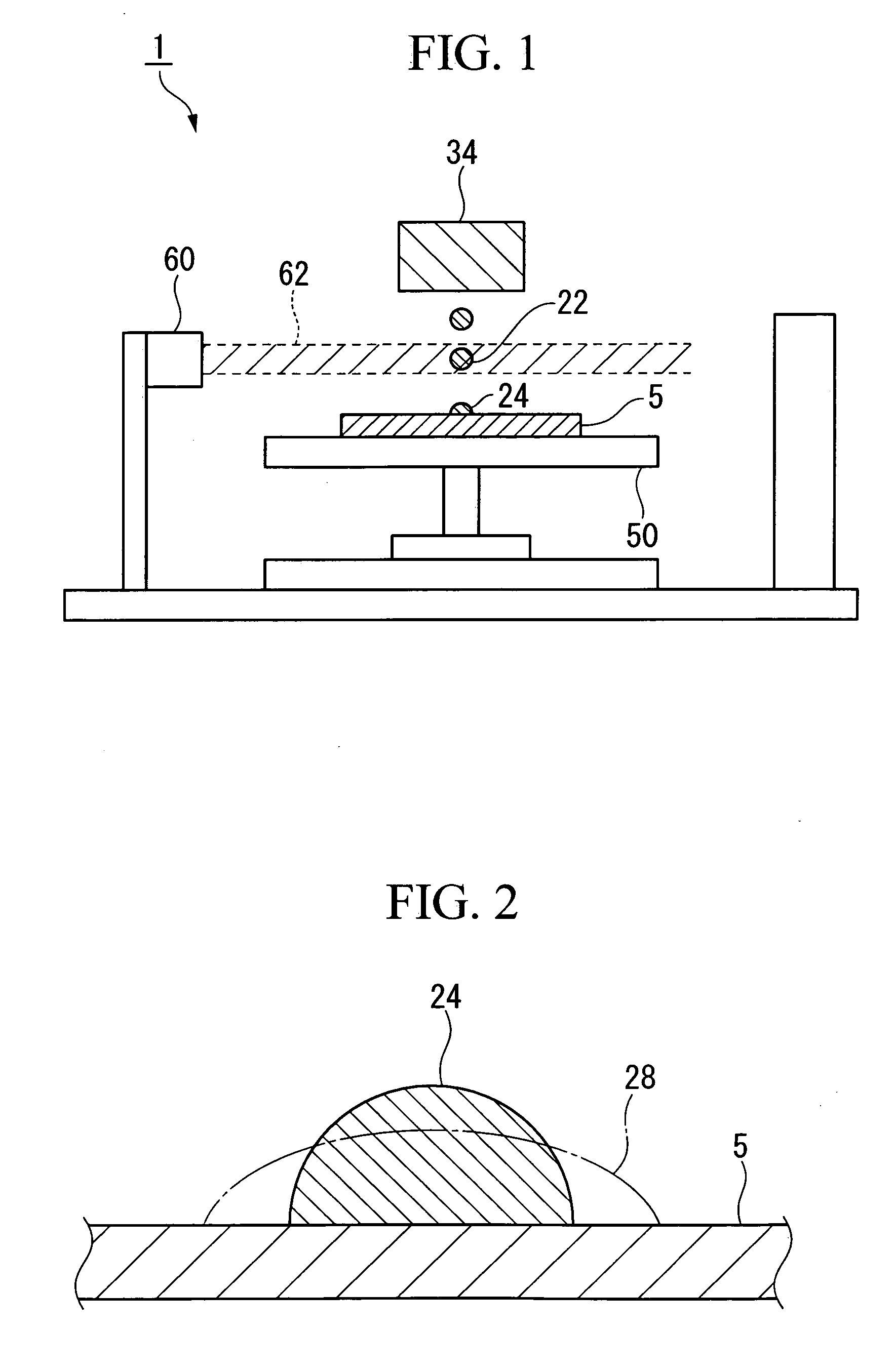
[0025]FIG. 1 is a schematic diagram illustrating a method for manufacturing a microlens and an apparatus for manufacturing the same according to this embodiment. In the method for manufacturing a microlens of this embodiment, liquid drops 22 containing a material for forming microlenses are ejected from the liquid drop ejection head 34 to make them land on the substrate 5, and the liquid drops 22 are irradiated with ultraviolet light 62 at least once at a time period between after the ejection of the liquid drops 22 and immediately after landing.

Material for Forming Microlens

[0026] As a material for forming microlenses, an ultraviolet light curable optical ...


PUM

PropertyMeasurementUnit
Timeaaaaaaaaaa

Abstract

A method for manufacturing a microlens includes: ejecting liquid drops containing a material for forming microlenses from a liquid drop ejection head to make the liquid drops land on a substrate; and irradiating the liquid drops with ultraviolet light at least once at a time period between after the ejection of the liquid drops and immediately after the landing of the liquid drops on the substrate. In addition, an apparatus for manufacturing a microlens, includes: a liquid drop ejection head that ejects liquid drops containing a material for forming microlenses; a table that supports a substrate above which the microlenses are to be formed; and an ultraviolet light radiating device that irradiates with ultraviolet light one of: the liquid drops that are flying from the liquid drop ejection head to the substrate; and the liquid drops that has landed on the substrate.

Description

BACKGROUND OF THE INVENTION [0001] 1. Field of the Invention [0002] The present invention relates to a method for manufacturing a microlens and to an apparatus for manufacturing the same. [0003] Priority is claimed on Japanese Patent Application No. 2004-209862, filed Jul. 16, 2004, the content of which is incorporated herein by reference. [0004] 2. Description of Related Art [0005] Recently, optical devices having a number of miniature lenses known as microlenses have become available. Examples of such optical devices include, for example, a light-emitting apparatus having a laser, an optical interconnection for an optical fiber, or a solid-state imaging element having a condenser lens for gathering incident light, or the like. [0006] The use of an ink jet method as a method for manufacturing such a microlens has been sought. In this method, liquid drops containing a material for forming microlenses are ejected on a substrate from miniature nozzles provided in an ink jet head, and ...

Claims


Application Information

Patent Timeline
IPC IPC(8): B29D11/00
CPCB29C41/12B29L2011/0016B29D11/00365B29C41/36G02B1/041G02B3/0012G02B3/005
Inventor HASEI, HIRONORI
Owner SEIKO EPSON CORP
Learn More