Projection objective having a high aperture and a planar end surface

a projection objective and high aperture technology, applied in the field of projection objects, can solve the problem of material not being transparent at 193 nm, and achieve the effect of moderate siz

Inactive Publication Date: 2006-01-19
CARL ZEISS SMT GMBH
View PDF99 Cites 119 Cited by
  • Summary
  • Abstract
  • Description
  • Claims
  • Application Information

AI Technical Summary

Benefits of technology

[0010] One object of the invention is to provide a high-aperture projection objective which circumvents the disadvantages of conventional designs with immersion media such as water or with lens materials such as fused...

Problems solved by technology

However, the material is ...

Method used


Image

  • Projection objective having a high aperture and a planar end surface
  • Projection objective having a high aperture and a planar end surface
  • Projection objective having a high aperture and a planar end surface

Examples


first embodiment

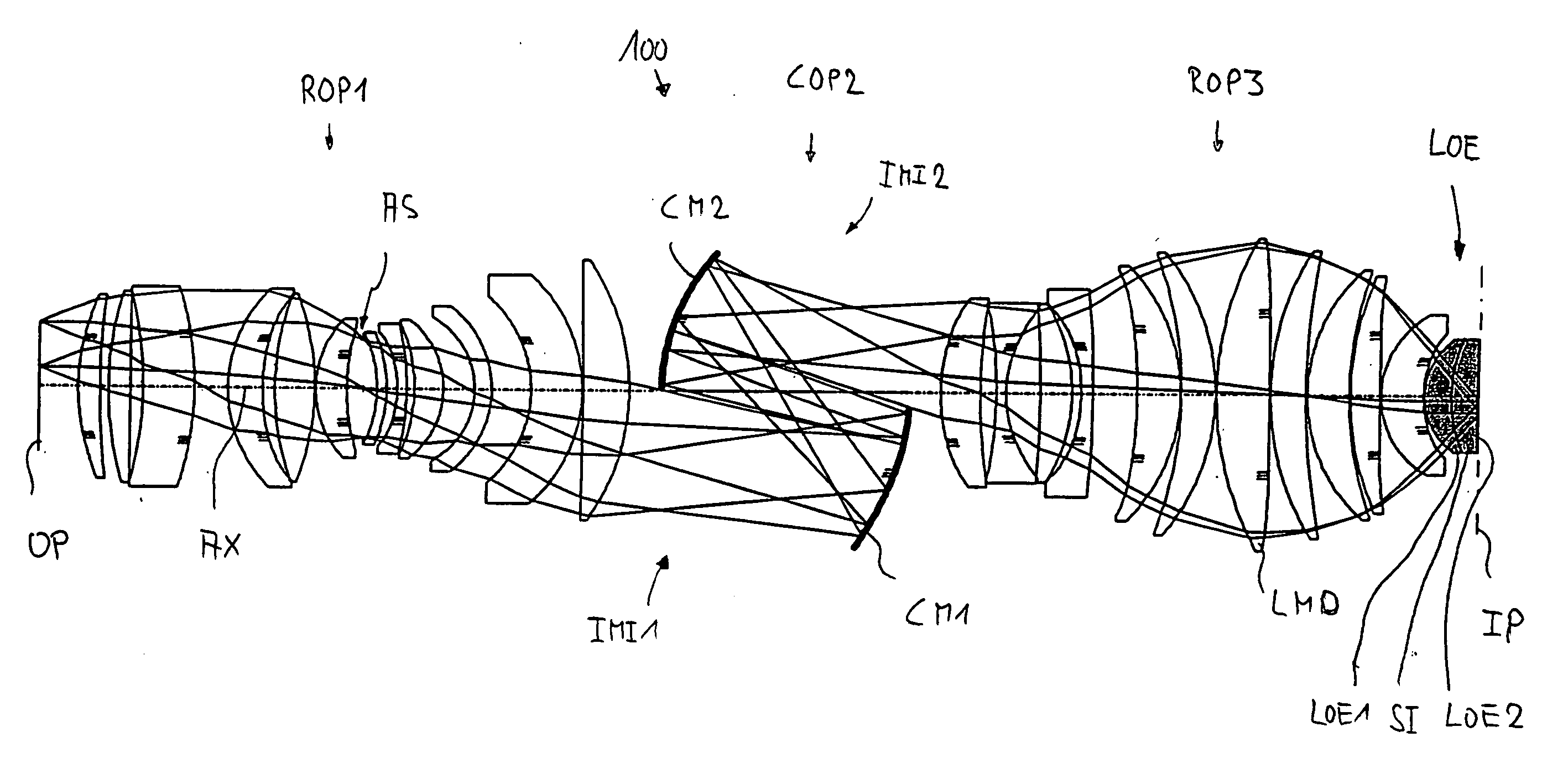
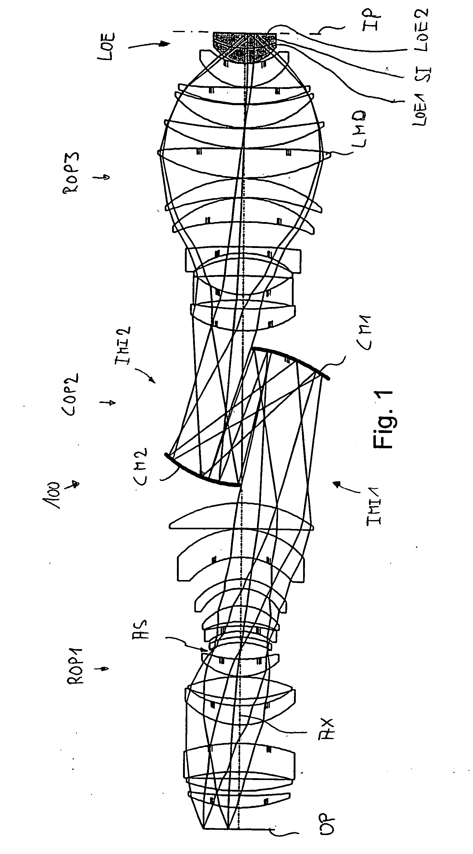
[0040]FIG. 1 shows a catadioptric projection objective 100 according to the invention designed for ca. 193 nm UV working wavelength. It is designed to project an image of a pattern on a reticle (or mask) arranged in the object plane OP into the image plane IP on a reduced scale, for example, 4:1, while creating exactly two real intermediate images IMI1 and IMI2. A first refractive objective part ROP1 is designed for imaging the pattern in the object plane into the first intermediate image IMI1, a second, catoptric (purely reflective) objective part COP2 images the first intermediate image IMI1 into the second intermediate image IMI2 at a magnification close to 1:1, and a third, refractive objective part ROP3 images the second intermediate image IMI2 onto the image plane IP with a strong reduction ratio. The second objective part COP2 comprises a first concave mirror CM1 having the concave mirror surface facing the object side, and a second concave mirror CM2 having the concave mirro...
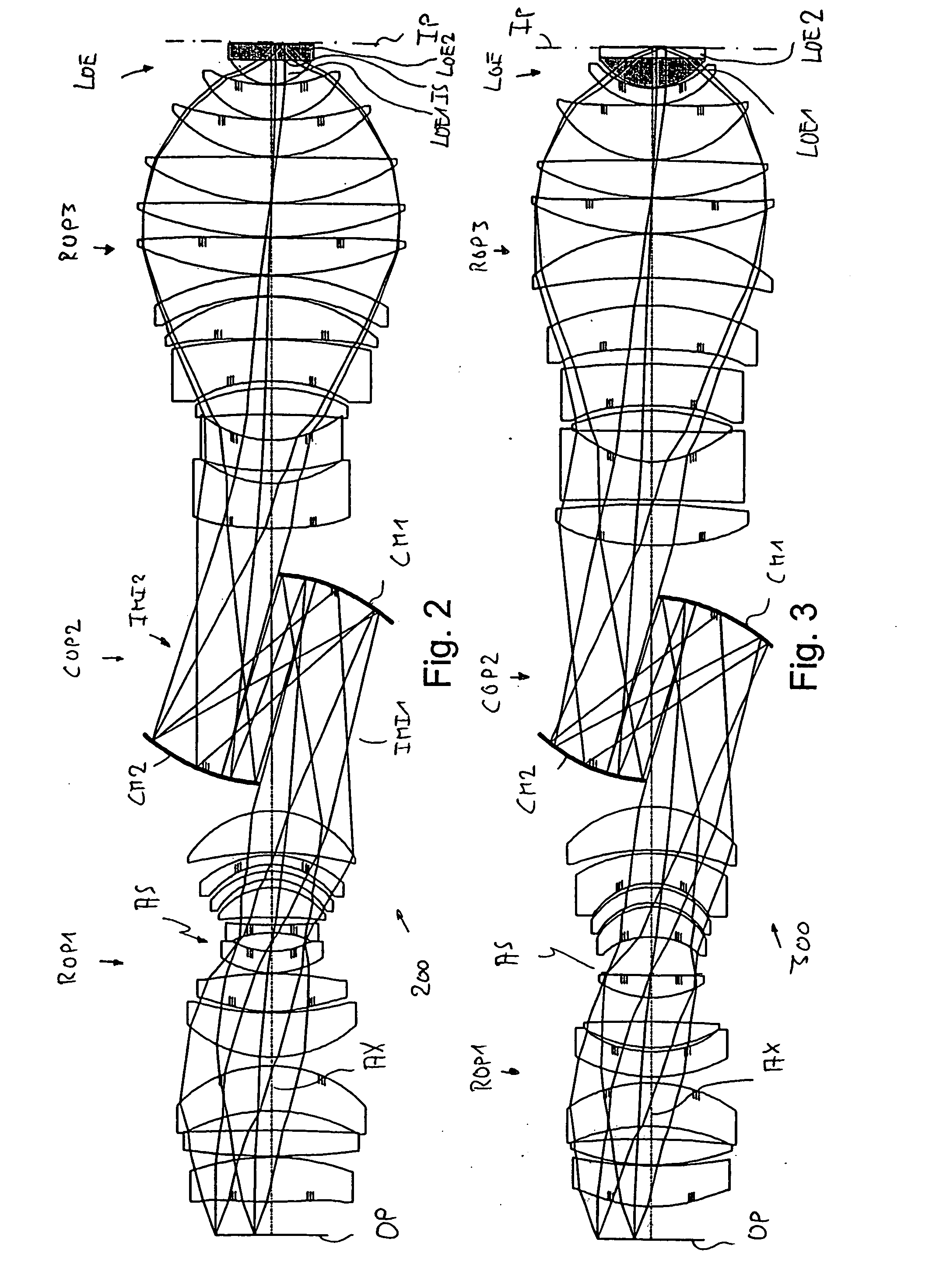
embodiment 3

[0057] In these cases, the NA is limited by the refractive index of the quartz glass. However, by comparison with a design having a last lens made from pure quartz glass the result upstream of the last lens is smaller beam angles and therefore also smaller diameters of the overall objective and lower sensitivities (interference susceptibilities to manufacturing tolerances) of the last lens element. In embodiment 3, at 135 mm the maximum lens diameter is now approximately 186 times the numerical aperture.

[0058] Of course, the present invention can also be used for objectives of low numerical aperture, in order to reduce substantially the diameter of previous projection objectives. This advantageously affects the price of the projection objective, since the amount of material can be reduced substantially.

[0059] The exemplary fourth embodiment (FIG. 4) shows a lithography objective 400 for 193 nm with a monolithic last lens made of sapphire and water (nH2O=1.43) as immersion medium fo...


PUM


Abstract

A projection objective for imaging a pattern provided in an object plane of the projection objective onto an image plane of the projection objective suitable for microlithography projection exposure machines has a plurality of optical elements transparent for radiation at an operating wavelength of the projection objective. At least one optical element is a high-index optical element made from a high-index material with a refractive index n≧1.6 at the operating wavelength.

Description

[0001] This application is a continuation-in-part application of international patent application PCT / EP2004 / 014062 filed on Dec. 10, 2004 and claiming priority from U.S. patent application Ser. No. 10 / 734,623 filed on Dec. 12, 2003, U.S. provisional application No. 60 / 530,623 filed on Dec. 19, 2003, U.S. provisional application No. 60 / 530,978 filed on Dec. 22, 2003, U.S. provisional application No. 60 / 536,248 filed on Jan. 14, 2004, U.S. provisional application No. 60 / 544,967 filed on Feb. 13, 2004, U.S. provisional application No. 60 / 568,006 filed on May 4, 2004, U.S. provisonal application No. 60 / 587,504 filed on Jul. 14, 2004, U.S. provisional application No. 60 / 612,823 filed on Sep. 24, 2004, U.S. provisional application No. 60 / 568,006 filed on May 4, 2004, U.S. provisional application No. 60 / 592,208 filed on Jul. 29, 2004, U.S. provisional application No. 60 / 617,674 filed on Oct. 13, 2004, U.S. provisional application No. 60 / 591,775 filed on Jul. 27, 2004 and German patent app...

Claims


Application Information

Patent Timeline
IPC IPC(8): G02B3/00
CPCB82Y10/00G02B17/0804G02B17/0812G03F7/70958G03F7/70225G03F7/70325G03F7/70341G02B17/0892
Inventor BEDER, SUSANNESINGER, WOLFGANGSCHUSTER, KARL-HEINZ
Owner CARL ZEISS SMT GMBH
Why Eureka
Try Eureka