Circuit-connecting material and circuit terminal connected structure and connecting method

a technology of connecting structure and circuit terminal, which is applied in the direction of non-conductive materials with dispersed conductive materials, synthetic resin layered products, printing, etc., can solve the problems of insufficient reaction, wiring coming off, separation or position deviation, etc., and achieves superior low-temperature rapid curability and long pot life

Inactive Publication Date: 2006-01-19
HITACHI CHEM CO LTD
View PDF34 Cites 38 Cited by
  • Summary
  • Abstract
  • Description
  • Claims
  • Application Information

AI Technical Summary

Benefits of technology

[0006] The present invention provides an electric and electronic circuit-connecting material having a superior low-temperature rapid curability and also having a long pot life.

Problems solved by technology

This is because catalyst type curing agents, which are inert at normal temperature, are used so that both short-time curability (rapid curability) and storage stability (storability) can be achieved to attain a better stability, and hence no sufficient reaction can take place when cured.
Hence, there has been a problem that the wiring comes off, separates or positionally deviates under connecting conditions for circuit-connecting materials making use of conventional epoxy resin adhesives.

Method used


Image

  • Circuit-connecting material and circuit terminal connected structure and connecting method
  • Circuit-connecting material and circuit terminal connected structure and connecting method
  • Circuit-connecting material and circuit terminal connected structure and connecting method

Examples


example 1

[0116] 50 g of phenoxy resin (available from Union Carbide Corp.; trade name: PKHC; average molecular weight: 45,000) was dissolved in a 50 / 50 (weight ratio) mixed solvent of toluene (boiling point: 110.6° C.; SP value: 8.90) and ethyl acetate (boiling point: 77.1° C.; SP value: 9.10) to form a solution with a solid content of 40%.

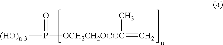
[0117] As the radical-polymerizable substance, trihydroxyethyl glycol dimethacrylate (available from Kyoeisha Chemical Co., Ltd.; trade name: 80MFA) was used.

[0118] As the free-radical-generating agent, a 50% by weight DOP solution of t-hexylperoxy-2-ethyl hexanoate (available from Nippon Oil & Fats Co., Ltd.; trade name: PERCURE HO) was used.

[0119] On the surfaces of polystyrene-core particles, nickel layers of 0.2 μm thick were provided. On the outsides of the nickel layers formed, gold layers of 0.04 μm thick were provided. Thus, conductive particles of 10 μm in average particle diameter were produced.

[0120] The phenoxy resin, the trihydroxyethyl gl...

examples 2 to 4

[0122] Circuit-connecting materials were obtained in the same manner as in Example 1 except that the trihydroxyethyl glycol dimethacrylate and a phosphate type acrylate (available from Kyoeisha Chemical Co., Ltd.; trade name: P2m) were used as radical-polymerizable substances and the solid weight ratio of the phenoxy resin / trihydroxyethyl glycol dimethacrylate / phosphate type acrylate was set to be 50 g / 49 g / 1 g (Example 2), 30 g / 69 g / 1 g (Example 3) or 70 g / 29 g / 1 g (Example 4).

[0123] Using these circuit-connecting materials, the circuits were connected in the same manner as in Example 1.

example 5

[0124] A circuit-connecting material was obtained in the same manner as in Example 1 except that the amount of the curing agent was changed to 2 g.

[0125] Using this circuit-connecting material, the circuits were connected in the same manner as in Example 1.


PUM

PropertyMeasurementUnit
half-life temperatureaaaaaaaaaa
light transmittanceaaaaaaaaaa

Abstract

A circuit-connecting material which is interposed between circuit electrodes facing each other and electrically connects the electrodes in the pressing direction by pressing the facing electrodes against each other; the circuit-connecting material comprising as essential components (1) a curing agent capable of generating free radicals upon heating, (2) a hydroxyl-group-containing resin having a molecular weight of 10,000 or more and (3) a radical-polymerizable substance. Also provided are a circuit terminal connected structure and a circuit terminal connecting method which make use of such a material.

Description

TECHNICAL FIELD [0001] This invention relates to a circuit-connecting material to be interposed between circuit electrodes facing each other and, the facing electrodes being pressed against each other, to electrically connect the electrodes in the pressing direction. It also relates to a circuit terminal connected structure and a circuit terminal connecting method. BACKGROUND ART [0002] Epoxy resin adhesives are widely used for various purposes of electric, electronic, construction, automobile, aircraft and so forth because they can attain a high bonding strength and have excellent water resistance and heat resistance. In particular, one-part epoxy resin adhesives are used in the form of films, pastes or powders because they make it unnecessary to mix the base resin and the curing agent and can be used with ease. In this case, it is general to attain specific performances by using epoxy resins, curing agents and modifiers in various combinations (e.g., Japanese Patent Application La...

Claims


Application Information

Patent Timeline
Patent Type & Authority Applications(United States)
IPC IPC(8): C08K5/00H01B1/20H01L21/60H01L23/29H05K3/32
CPCC08G18/0823C08G18/2865C08G18/3206C08G18/3821C08G18/672C08K5/14C08K5/1515C08K5/521C08L9/02C08L13/00C09D5/24C09D175/16H01B1/20H01L23/293H01L24/81H01L24/83H01L2224/16225H01L2224/73204H01L2224/81801H01L2224/83192H01L2224/838H01L2924/01002H01L2924/01005H01L2924/01011H01L2924/01015H01L2924/01027H01L2924/01029H01L2924/01046H01L2924/01047H01L2924/0105H01L2924/01052H01L2924/01061H01L2924/01073H01L2924/01077H01L2924/01078H01L2924/01079H01L2924/01082H01L2924/04953H01L2924/0781H01L2924/09701H01L2924/14H01L2924/19041H01L2924/19043H05K3/323H05K3/361H05K2201/0133H01L24/29H01L2224/2919H01L2924/01006H01L2924/01019H01L2924/01023H01L2924/01033H01L2924/01045H01L2924/01067H01L2924/014H01L2924/0665H01L2224/2929H01L2224/29339H01L2224/29344H01L2224/29347H01L2224/29355H01L2224/29393H01L2924/00013H01L2924/07811Y10T428/10Y10T428/2852C08G18/8016C08L2666/16H01L2924/00014H01L2924/00H01L2224/29099H01L2224/29199H01L2224/29299C09K2323/00Y10T428/31504Y10T428/31511Y10T428/31515Y10T428/31855Y10T428/31935Y10T428/31942H01L2224/05611H01L2224/05639H01L2224/05644H01L2224/05669H01L2224/05599H01L2224/0555H01L2224/0556H01L2224/0554H01L2224/05568H01L2224/05573
Inventor WATANABE, ITSUOFUJINAWA, TOHRUARIFUKU, MOTOHIROKANAZAWA, HOUKOKUWANO, ATSUSHI
Owner HITACHI CHEM CO LTD
Why Eureka
Try Eureka