
Expandable medical device for delivery of beneficial agent

a medical device and beneficial agent technology, applied in the field of tissue-supporting medical devices, can solve the problems of difficulty in accurately placing the stent or finding and retrieving stents that subsequently become dislodged and lost in the circulatory system, stents are often unstable, and display a tendency to buckle, etc., to eliminate buckling and twisting of structural features during stent deployment, and increase the available depth

Inactive Publication Date: 2006-01-19
INNOVATIONAL HLDG LLC
View PDF11 Cites 0 Cited by
  • Summary
  • Abstract
  • Description
  • Claims
  • Application Information

AI Technical Summary

Benefits of technology

The stent achieves stable expansion with reduced recoil and increased agent delivery, allowing for secure crimping onto delivery catheters and improved mechanical properties, enhancing the effectiveness of stent placement and reducing restenosis risks.

Problems solved by technology

However, materials this thin are not visible on conventional fluoroscopic and x-ray equipment and it is therefore difficult to place the stents accurately or to find and retrieve stents that subsequently become dislodged and lost in the circulatory system.
When expanded, these struts are frequently unstable, that is, they display a tendency to buckle, with individual struts twisting out of plane.
Excessive protrusion of these twisted struts into the bloodstream has been observed to increase turbulence, and thus encourage thrombosis.
These secondary procedures can be dangerous to the patient due to the risk of collateral damage to the lumen wall.
Over-expansion is potentially destructive to the lumen tissue.
Large recoil also makes it very difficult to securely crimp most known stents onto delivery catheter balloons.
As a result, slippage of stents on balloons during interlumenal transportation, final positioning, and implantation has been an ongoing problem.
Another problem with known stent designs is non-uniformity in the geometry of the expanded stent.
Non-uniform expansion can lead to non-uniform coverage of the lumen wall creating gaps in coverage and inadequate lumen support.
Further, over expansion in some regions or cells of the stent can lead to excessive material strain and even failure of stent features.
This problem is potentially worse in low expansion force stents having smaller feature widths and thicknesses in which manufacturing variations become proportionately more significant.
This process of unfolding the balloon causes uneven stresses to be applied to the stent during expansion of the balloon due to the folds causing the problem non-uniform stent expansion.
However, the “recoil” problem after expansion is significantly greater with Nitinol than with other materials.
Nitinol is also more expensive, and more difficult to fabricate and machine than other stent materials, such as stainless steel.
These forces can cause substantial damage to tissue if misapplied.
In addition to the above-mentioned risks to a patient, restenosis is a major complication which can arise following the implantation of stents, using stent devices such as those described above, and other vascular interventions such as angioplasty.
To correct this problem, additional revascularization procedures are frequently required, thereby increasing trauma and risk to the patient.
In either case, it has proven difficult to deliver a sufficient amount of beneficial agent to the trauma site so as to satisfactorily prevent the growth of scar tissue and thereby reduce the likelihood of restenosis.
Furthermore, increasing the effective stent thickness (e.g., by providing increased coatings of the beneficial agent) is undesirable for a number of reasons, including increased trauma to the vessel lumen during implantation and reduced flow cross-section of the lumen after implantation.
Moreover, coating thickness is one of several factors that affect the release kinetics of the beneficial agent, and limitations on thickness thereby limit the range of release rates, durations, and the like that can be achieved.

Method used


Image

  • Expandable medical device for delivery of beneficial agent
  • Expandable medical device for delivery of beneficial agent
  • Expandable medical device for delivery of beneficial agent

Examples


Embodiment Construction

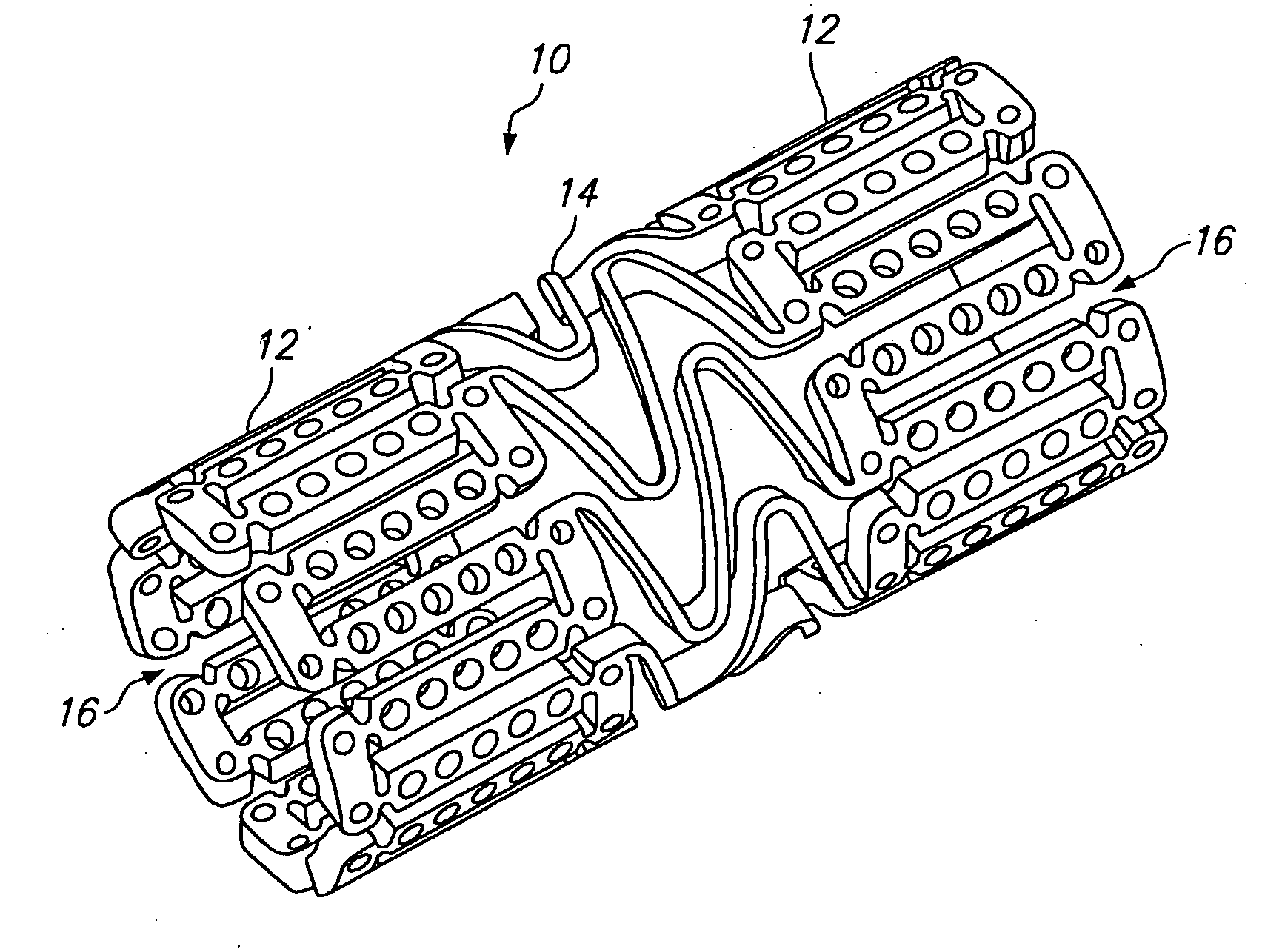
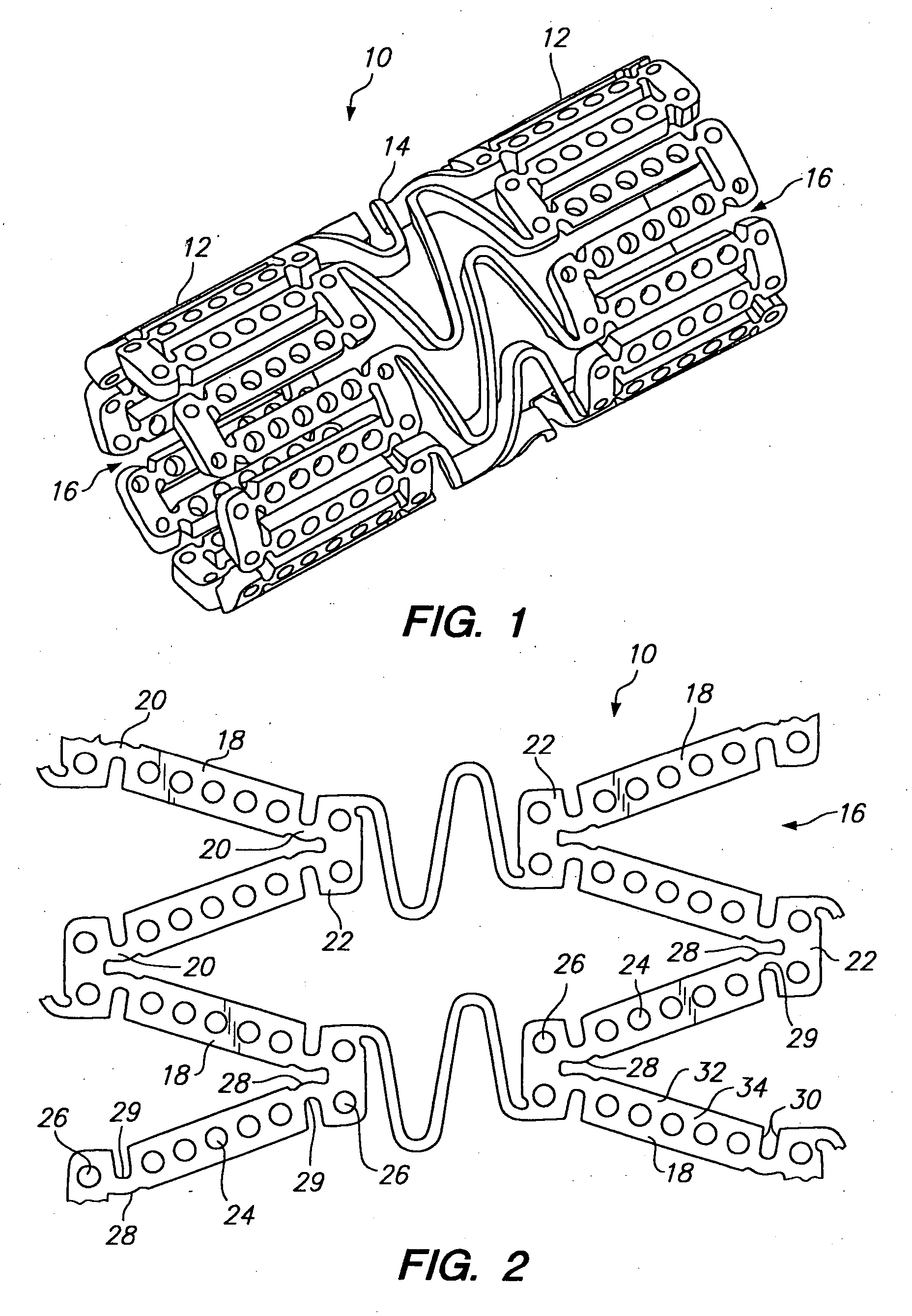
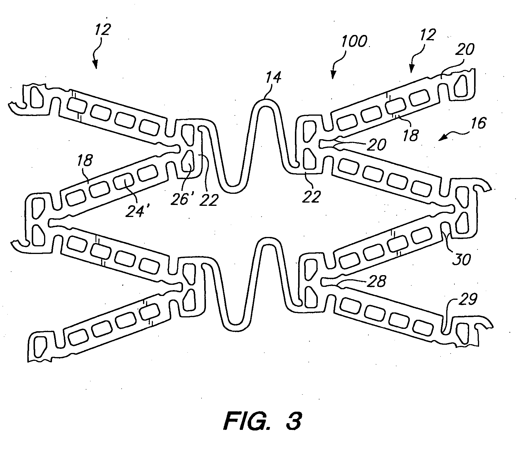
[0039] Referring to FIGS. 1 and 2, a tissue supporting device in accordance with a preferred embodiment of the present invention is shown generally by reference numeral 10. The tissue supporting device 10 includes a plurality of cylindrical tubes 12 connected by S-shaped bridging elements 14. The bridging elements 14 allow the tissue supporting device to bend axially when passing through the tortuous path of the vasculature to the deployment site and allow the device to bend when necessary to match the curvature of a lumen to be supported. The S-shaped bridging elements 14 provide improved axial flexibility over prior art devices due to the thickness of the elements in the radial direction which allows the width of the elements to be relatively small without sacrificing radial strength. For example, the width of the bridging elements 14 may be about 0.0015-0.0018 inches (0.0381-0.0457 mm). Each of the cylindrical tubes 12 has a plurality of axial slots 16 extending from an end surfa...


PUM

PropertyMeasurementUnit
pressureaaaaaaaaaa
pressuresaaaaaaaaaa
pressuresaaaaaaaaaa

Abstract

An expandable medical device having a plurality of elongated struts, the plurality of elongated struts being joined together to form a substantially cylindrical device which is expandable from a cylinder having a first diameter to a cylinder having a second diameter, and the plurality of struts each having a strut width in a circumferential direction. At least one of the plurality of struts includes at least one opening extending at least partially through a thickness of said strut. A beneficial agent may be loaded into the opening within the strut. The expandable medical device may further include a plurality of ductile hinges formed between the elongated struts, the ductile hinges allowing the cylindrical device to be expanded or compressed from the first diameter to the second diameter by deformation of the ductile hinges.

Description

CROSS-REFERENCE TO RELATED APPLICATIONS [0001] This application is a continuation-in-part of pending U.S. application Ser. No. 09 / 183,555, filed Oct. 29, 1998, which claims the benefit of Provisional Application Ser. No. 60 / 079,881, filed Mar. 30, 1998.BACKGROUND OF THE INVENTION [0002] 1. Field of the Invention [0003] The present invention relates to tissue-supporting medical devices, and more particularly to expandable, non-removable devices that are implanted within a bodily lumen of a living animal or human to support the organ and maintain patency, and that can deliver a beneficial agent to the intervention site. [0004] 2. Summary of the Related Art [0005] In the past, permanent or biodegradable devices have been developed for implantation within a body passageway to maintain patency of the passageway. These devices are typically introduced percutaneously, and transported transluminally until positioned at a desired location. These devices are then expanded either mechanically,...

Claims


Application Information

Patent Timeline
Patent Type & Authority Applications(United States)
IPC IPC(8): A61F2/06A61F2/00A61F2/82A61L27/04A61L27/54A61M29/02
CPCA61F2/0077A61F2/91A61F2250/0068A61F2002/91541A61F2002/91558A61F2/915A61F2/82A61L27/04A61L27/54A61M29/02
Inventor SHANLEY, JOHN F.EIGLER, NEAL L.
Owner INNOVATIONAL HLDG LLC
Learn More