Rolling element and method of producing the same

a technology of rolling element and rolling element, which is applied in the direction of metallic material coating process, solid-state diffusion coating, portable lifting, etc., can solve the problems of affecting the economic efficiency of machining of gears, and affecting the economic efficiency of machining. , to achieve the effect of improving the economic efficiency, improving the bending fatigue strength and pitting resistance of the surface layer of the rolling element, and improving the economic efficiency of machining

Inactive Publication Date: 2006-02-02
KOMATSU LTD
View PDF29 Cites 14 Cited by
  • Summary
  • Abstract
  • Description
  • Claims
  • Application Information

AI Technical Summary

Benefits of technology

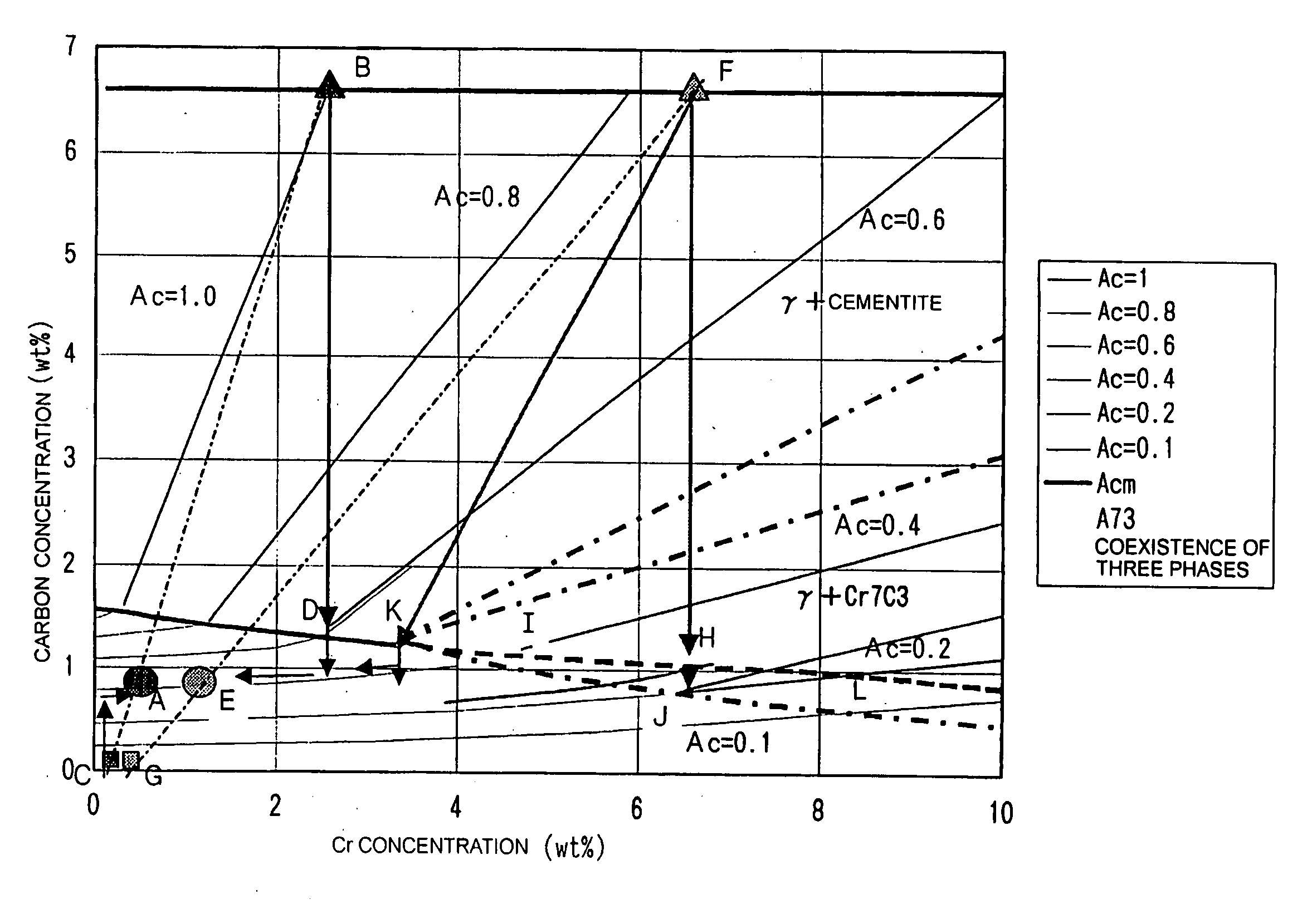
[0081] With this method, a rolling element can be produced from a steel material having lower carbon content than that of the steel material described earlier, so that the economical efficiency of machining of a gear for instance can be improved. In addition, the need to provide expensive induction hardening equipment used for the above-noted rapid cooling is obviated, leading to an improvement in economical efficiency. Herein, the carbon concentration of the rolling contact surface is preferably in the range of 0.9 to 1.5 wt %.
[0082] The method may include a mechanical treatment step in which a compressive residual stress of 50 kgf / mm2 or more is generated, by a treatment such as shot peening, in a part or the whole of the surface layer of the rolling element after the induction hardening treatment step. With this arrangement, the bending fatigue strength and pitting resistance of the surface layer of the rolling element can be increased.

Problems solved by technology

Construction machines and earth-moving machines often stride obstacles such as rocks and structures during traveling and break up such obstacles while making a turn.
Therefore, the gears of the reducer used for running and turning the vehicle body receive impulsive load.
Under such a condition, carburized / quenched gears are susceptible to damage.
Induction hardened gears have higher toughness than carburized / quenched gears, but where induction hardened gears are used under a high interface pressure of 150 kgf / mm2 more as noted earlier, defects in terms of contact fatigue strength (e.g., pitting, scuffing and premature wear of tooth flanks) are likely to occur.

Method used


Image

  • Rolling element and method of producing the same
  • Rolling element and method of producing the same
  • Rolling element and method of producing the same

Examples


example 1

The pitting resistance of quenched, tempered carbon steels and carburized, quenched, case-hardened steels

(Preliminary Test)

[0111] In this example, a roller pitting test was conducted using the test specimens shown in FIG. 4 and various, quenched, tempered carbon steels and carburized, quenched, case-hardened steels were checked in terms of pitting resistance to investigate the rolling fatigue strength of the tooth flanks of gears under a sliding contact condition. Table 1 shows the chemical compositions of the various carbon steels and case-hardened steels used in this example. These steel materials were respectively shaped into the small rollers shown in FIG. 4(a) and the test specimens No. 1, 2 and 4 were further subjected to water quenching after heating at 820° C. for 30 minutes, and then tempered at 160° C. for 3 hours, followed by testing. The test specimen Nos. 3 and 4 were quench-hardened, at their rolling contact surfaces, using a 40 kHz high-frequency power source after...

example 2

Checking of Temper Softening Resistance

[0117] Table 2 shows the alloy compositions employed in this example. Thermal treatment was carried out in such a way that after heated at 810 to 870° C. for 30 minutes, each test specimen was subjected to water cooling and then tempering at 300° C. and 350° C. for 3 hours. Thereafter, the Rockwell hardness HRC of each test specimen was checked and the effect of addition of each alloy element on the hardness was analyzed.

TABLE 2TPNo.CSiAlMnNiCrMoVBNo. 60.451.450.461.490.520.140.0018No. 70.491.450.461.011.030.150.0019No. 80.470.310.462.011.030.150.0019No. 90.490.290.451.51.490.230.0019No. 100.361.770.60.620.110.0026No. 110.450.950.660.011.290.50.0029No. 120.390.931.020.080.970.950.5No. 130.430.260.441.010.480.001No. 140.470.250.41.011.050.0018No. 150.461.50.410.510.002No. 160.450.240.41.020.480.310.0011No. 170.451.460.390.960.980.001No. 180.410.250.3510.490.0017No. 190.522.30.570.11No. 200.980.270.481.47No. 210.550.230.71No. 220.770.210.74No....

example 3

An Improvement in Pitting Resistance by Use of Steel Material Having Excellent Temper Softening Resistance—1

[0122] Table 3 shows the alloy compositions of the steel materials used in this example. After induction hardened under the same induction heating condition as in Example 1, each test specimen was tempered at 160° C. for 3 hours and then subjected to a roller pitting test.

TABLE 3VOLUMEINTERFACEPERCENT OFPRESSURE THATCSiAlMnNiCrMoVTiCEMENTITECAUSES SEIZURENo. P10.580.210.0240.410.462350No. P20.630.580.0210.380.462350No. P30.610.251.470.930.981.040.353400No. P40.831.010.310.550.960.385375No. P50.730.710.0280.460.490.194425SCM420 + GCQT300SCM440 + QT275SUJ2 + QT400S55C + QT275

[0123] The dispersion amount of the cementite contained in the rolling contact surface layer of each test specimen is also written in Table 3. The test for checking pitting resistance was carried out under substantially the same condition as in Example 1 and the test result is shown in FIG. 8. The pitting...


PUM

PropertyMeasurementUnit
particle diameteraaaaaaaaaa
average particle diameteraaaaaaaaaa

Abstract

There is provided an inexpensive rolling element used under high interface pressure such as induction hardened gears, the rolling element being improved in the seizure resistance of its tooth flanks and having a temper hardness of HRC 50 or more at 300° C. To this end, the rolling element is made from a steel material containing at least 0.45 to 1.5 wt % C and one or more alloy elements selected from 0.1 to 0.5 wt % V and 0.3 to 1.5 wt % Cr, and has a rolling contact surface layer having a structure tempered at low temperature in which 2 to 18% by volume cementite disperses in a martensite parent phase formed by induction heating and cooling and containing 0.25 to 0.8 wt % carbon solid-dissolving therein.

Description

CROSS-REFERENCE TO RELATED APPLICATION [0001] This application is a Divisional application of U.S. application Ser. No. 10 / 790,931 filed on Mar. 1, 2004.TECHNICAL FIELD [0002] The present invention relates to a rolling element such as gears and a method of its production, the rolling element being produced by quench hardening its rolling contact surface layer through induction hardening treatment to enhance pitting resistance. BACKGROUND ART [0003] Up to now, there have been commonly used, in the reducers of construction machines and earth-moving machines, gears produced by applying carburizing / quenching or carbonitriding / quenching to Scr-based, SCM-based or SNCM-based low carbon steel, since high contact fatigue strength (no less than 200 kgf / mm2) is considered to be an important factor. Some gears used under comparatively low interface pressure (up to 150 kgf / mm2) are produced by applying thermal treatment such as induction hardening to steel having a carbon concentration of 0.35 ...

Claims


Application Information

Patent Timeline
Patent Type & Authority Applications(United States)
IPC IPC(8): C23C8/32C23C8/22F16H55/06C21D1/06C21D1/10C21D1/32C21D1/78C21D7/06C21D9/32C22C38/00C22C38/24C22C38/50C23C8/80
CPCC21D1/10C21D1/32C21D1/78C21D7/06C23C8/80C21D2211/003C21D2211/008C23C8/22C23C8/32C21D9/32Y10S148/906Y10S384/912Y02P10/25
Inventor TAKAYAMA, TAKEMORIFURUMOTO, MASANARINAKAO, CHIKARAMORIOKA, NORIKO
Owner KOMATSU LTD
Why Eureka
Try Eureka