Method and control circuitry for improved-performance switch-mode converters

a technology of switch-mode converter and control circuit, which is applied in the field of switching power converter, can solve the problems of distorted line voltage shape, low power transmission efficiency, and possible interference with other electrical units connected to the power line, and achieves the effects of increasing reliability and flexibility, simplifying construction, and large bandwidth

Inactive Publication Date: 2006-02-02
GREEN POWER TECH LTD
View PDF13 Cites 207 Cited by
  • Summary
  • Abstract
  • Description
  • Claims
  • Application Information

AI Technical Summary

Benefits of technology

[0025] It may be further desirable that a controller for an APFC system be able to be operated in an advanced manner in which there is no need to sample the input voltage, and be able to cope with the large bandwidths required by such a control scheme.
[0026] It is an objective of the present invention to provide circuitry for simplifying the construction, and increasing the reliability and flexibility, of controllers for switch-mode power systems.
[0027] It is another objective of the present invention to provide economical digital circuitry for improv

Problems solved by technology

Injection of high harmonics into the power line, and poor power factor in general, are known to cause many problems.
Among these are lower efficiency of power transmission, possible interference to other electrical units connected to the power line and distorted shape of the line voltage.
Cost is of great concern considering the fact that the APFC is generally an additional expense not directly related to the basic functionality of the equipment in which the APFC converter is included.
Notwithstanding the many advantages of digital controllers, cost is still an obstacle that makes wide usage of this approach uneconomical in many applications.
The main reason for the high cost is the requirement for a relatively wide-bandwidth control loop.
In fact, a fast-responding outer loop is considered harmful because it will cause undesired distortion of the input current due to modulation by the ac ripple of the output voltage.
Such a DC-DC converter is typically rather insensitive to variations in input voltage.
This significantly increases the cost of the digital solution as compared to the analog approach for APFC controllers.
Another engineering issue that needs to attention in the design of AC-DC converters is the control of the inrush current.
That

Method used


Image

  • Method and control circuitry for improved-performance switch-mode converters
  • Method and control circuitry for improved-performance switch-mode converters
  • Method and control circuitry for improved-performance switch-mode converters

Examples


Embodiment Construction

[0066] The present invention is of a power converter which can provide a desired output voltage to a load while presenting the power line with a load having desired characteristics, such as, for example, unity power factor.

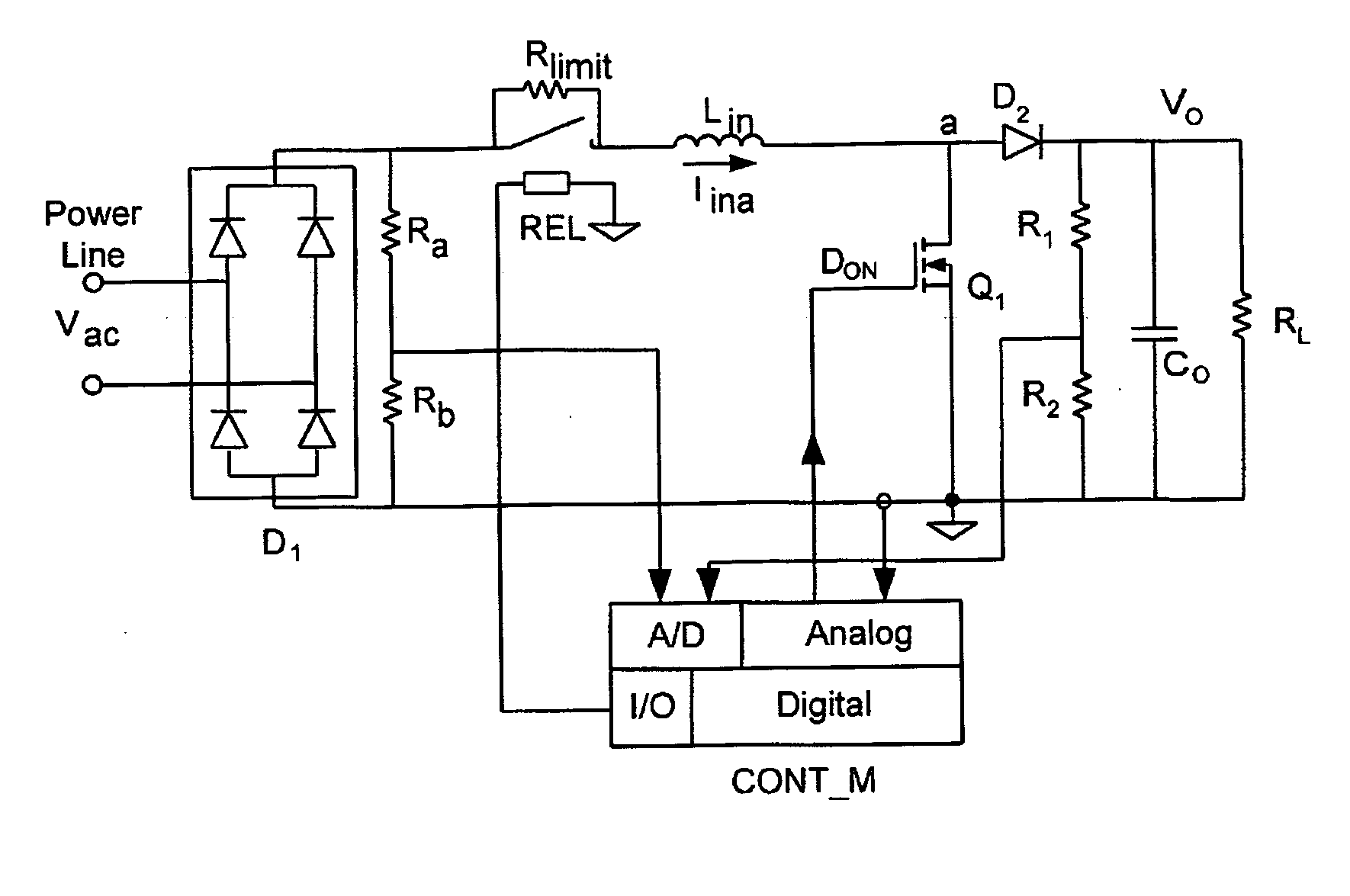
[0067] Referring now to the drawings, FIG. 6 illustrates a possible embodiment of an APFC stage according to the present invention. The power stage includes an inductor Lin, a main switch Q1, a main diode D2, and an output capacitor Co. The power stage also includes a relay REL having contacts connected in series with inductor Lin. A charging resistor Rlimit is placed across the contacts of relay REL so that when those contacts are non-conducting current will flow will be limited by Rlimit. According to the present invention, a mixed mode controller CONT_M, having an analog section and a digital section, samples input voltage, input current Iina, and output voltage Vo. The input current signal is processed according to a predetermined control algorithm by the ana...


PUM


Abstract

A system and method for supplying power to a load and for controlling the power factor presented to the power line. Output voltage is controlled by a digital, outer, control loop, and inner, analog, control loop causes the input current to be substantially proportional to the input voltage at any particular point in the power line cycle. Thus, the system presents a load to the power line that appears to be purely resistive. The use of an analog multiplier is not required, nor is sampling of input voltage. Limiting of inrush current provides for brown-out protection and soft-start.

Description

RELATED APPLICATIONS [0001] This application claims the benefit of earlier-filed provisional application Ser. No. 60 / 592,377, filed on Aug. 2, 2004 and entitled “Method and Controller Circuitry for Improved Performance Switch-Mode Converters”.FIELD AND BACKGROUND OF THE INVENTION [0002] The present invention relates to the field of switching power converters. More particularly, the present invention relates to a method and circuitry for improving the input current and / or output voltage regulation of switching power converters. [0003] Currently, there are several types of power converters which are widely used for DC-to-DC, DC-to-AC, AC-to-DC and AC-to-AC power conversion. In some applications the purpose of the converter is to provide a regulated output voltage. In other applications the purpose of the power conversion scheme is to shape the input current at the input terminals of the converter so that the input current will follow the shape of the input voltage. For example, in a p...

Claims


Application Information

Patent Timeline
IPC IPC(8): G05F1/656
CPCY02B70/126H02M1/4225Y02B70/10
Inventor BEN-YAAKOV, SHMUELZELTSER, ILYA
Owner GREEN POWER TECH LTD
Why Eureka
Try Eureka