Locating a mobile station and applications therefor

a mobile station and application technology, applied in the field of system and method for locating people or objects, can solve the problems of high cost, special-purpose electronics are required, and the system is generally only effective in line-of-sight conditions, so as to improve telephony coverage, accurately locate people and/or objects, and ensure the effect of signal discrimination

Inactive Publication Date: 2006-02-02
FINETRAK LLC
View PDF99 Cites 484 Cited by
  • Summary
  • Abstract
  • Description
  • Claims
  • Application Information

AI Technical Summary

Benefits of technology

[0041] It is an objective of the present invention to provide a system and method for determining wireless location using one or more commercial mobile radio telecommunication systems for accurately locating people and / or objects in a cost effective manner. Related objectives for the present invention include providing a system and method that:

Problems solved by technology

However, these systems have drawbacks that include high expense in that special purpose electronics are required.
Furthermore, the systems are generally only effective in line-of-sight conditions, such as rural settings.
Radio wave surface reflections, refractions and ground clutter cause significant distortion, in determining the location of a signal source in most geographical areas that are more than sparsely populated.
Moreover, these drawbacks are particularly exacerbated in dense urban canyon (city) areas, where errors and / or conflicts in location measurements can result in substantial inaccuracies.
However, the GPS is impractical in many applications.
Accordingly, inclement weather conditions, such as clouds, terrain features, such as hills and trees, and buildings restrict the ability of the GPS receiver to determine its position.
Furthermore, the initial GPS signal detection process for a GPS receiver is relatively long (i.e., several minutes) for determining the receivers position.
Such delays are unacceptable in many applications such as, for example, emergency response and vehicle tracking.
These systems have been found to be awkward and have met with limited success.
Such systems have also met with limited success due, for example, to the limited reception of the satellite signals and the added expense and complexity of the electronics required for an inexpensive location mobile station or handset for detecting and receiving the GPS signals from the satellites.
The behavior of a mobile radio signal in the general environment is unique and complicated.
Efforts to perform correlation between radio signals and distance between a base station and a mobile station are similarly complex.
Sheffer acknowledges that terrain variations affect accuracy, although as noted above, Sheffer's disclosure does not account for a sufficient number of variables, such as fixed and variable location shadow fading, which are typical in dense urban areas with moving traffic.
Rays penetrating buildings then emanating outside a building were neglected.
However, a substantial difficulty with the two-ray model in practice is that it requires a substantial amount of data regarding building dimensions, geometry, street widths, antenna gain characteristics for every possible ray path, etc.
Additionally, it requires an inordinate amount of computational resources and such a model is not easily updated or maintained.
Unfortunately, in practice clutter geometry and building heights are random.
Moreover, data of sufficient detail is extremely difficult to acquire, and regression standard fit errors are poor; i.e., in the general case, these errors were found to be 40-60 dB.
Thus the two-ray model approach, although sometimes providing an improvement over single ray techniques, still did not predict RF signal characteristics in the general case to level of accuracy desired (<10 dB).
Although some data held very correlation, other data and environments produced poor results.
Accordingly, his results appear unreliable for use in general location context.
However, these results alone have not been sufficiently robust and general to accurately locate an mobile station, due to the variable nature of urban clutter spatial arrangements.
However, in the worst-case scenario both fading margins are simultaneously exceeded, thus causing a fading margin overload.

Method used


Image

  • Locating a mobile station and applications therefor
  • Locating a mobile station and applications therefor
  • Locating a mobile station and applications therefor

Examples


Embodiment Construction

[0282] Various digital wireless communication standards have been introduced such as code division multiple access (CDMA) and Time Division Multiple Access (TDMA) (e.g., Global Systems Mobile (GSM). These standards provide numerous enhancements for advancing the quality and communication capacity for wireless applications. Referring to CDMA, this standard is described in the Telephone Industries Association standard IS-95, for frequencies below 1 GHz, and in J-STD-008, the Wideband Spread-Spectrum Digital Cellular System Dual-Mode Mobile Station-Base station Compatibility Standard, for frequencies in the 1.8-1.9 GHz frequency bands.

[0283] Additionally, CDMA general principles have been described, for example, in U.S. Pat. No. 5,109,390, Diversity Receiver in a CDMA Cellular Telephone System, by Gilhousen, et al, filed Nov. 7, 1989. There are numerous advantages of such digital wireless technologies such as CDMA radio technology. For example, the CDMA spread spectrum scheme exploits...


PUM


Abstract

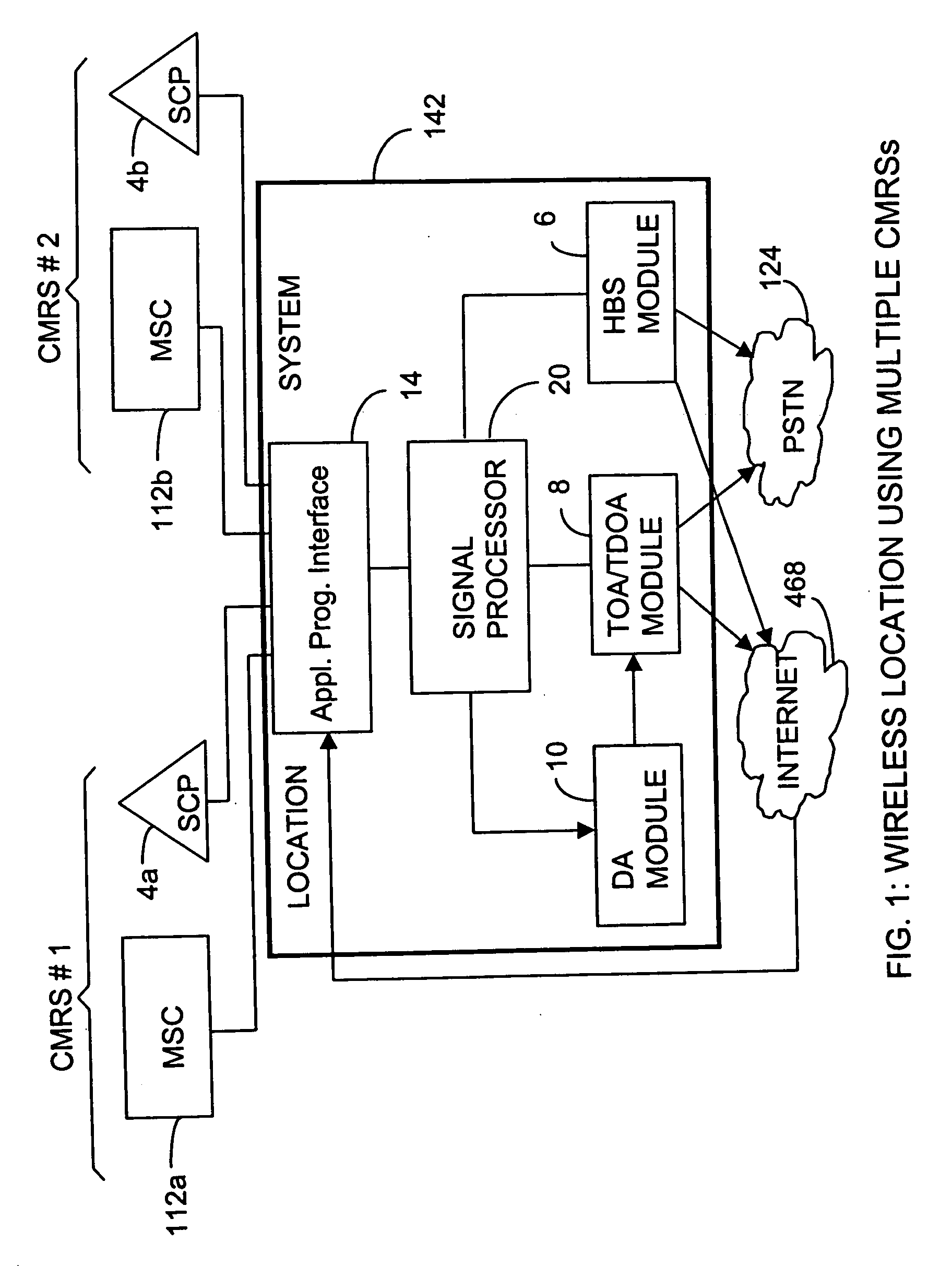
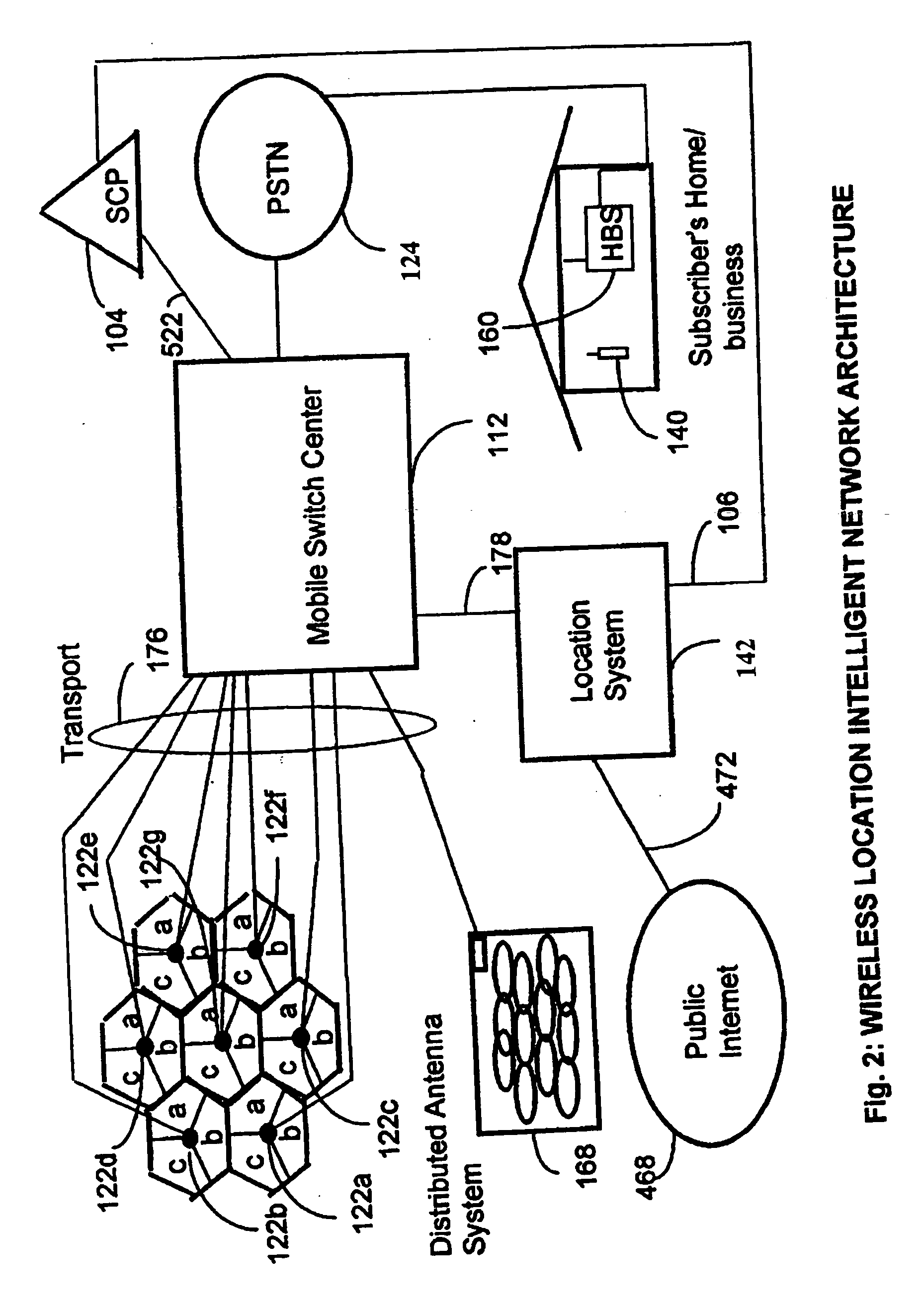
A location system is disclosed for wireless telecommunication infrastructures. The system is an end-to-end solution having one or more location systems for outputting requested locations of hand sets or mobile stations (MS) based on, e.g., AMPS, NAMPS, CDMA or TDMA communication standards, for processing both local mobile station location requests and more global mobile station location requests via, e.g., Internet communication between a distributed network of location systems. The system uses a plurality of mobile station locating technologies including those based on: (1) two-way TOA and TDOA; (2) home base stations and (3) distributed antenna provisioning. Further, the system can be modularly configured for use in location signaling environments ranging from urban, dense urban, suburban, rural, mountain to low traffic or isolated roadways. The system is useful for 911 emergency calls, tracking, routing, people and animal location including applications for confinement to and exclusion from certain areas.

Description

RELATED APPLICATIONS [0001] The present application is: [0002] a continuation of U.S. application Ser. No. 09 / 820,584 filed Mar. 28, 2001, and [0003] a continuation-in-part of U.S. application Ser. No. 09 / 194,367 filed Nov. 24, 1998; U.S. application Ser. No. 09 / 820,584 is a continuation of U.S. application Ser. No. 09 / 230,109 filed Jul. 8, 1999 (now U.S. Pat. No. 6,236,365) which is the National Stage of International Application No. PCT / US97115933 filed Sep. 8, 1997 which, in turn, claims the benefit of the following three applications: U.S. Provisional Application No. 60 / 056,603 filed Aug. 20, 1997, U.S. Provisional Application No. 60 / 044,821 filed Apr. 25, 1997; and U.S. Provisional Application No. 60 / 025,855 filed Sep. 9, 1996; U.S. application Ser. No. 09 / 194,367 is the National Stage of International Application No. PCT / US97 / 15892, filed Sep. 8, 1997, which claims the benefit of the following three provisionals: U.S. Provisional Application No. 60 / 056,590 filed Aug. 20, 1997;...

Claims


Application Information

Patent Timeline
Patent Type & Authority Applications(United States)
IPC IPC(8): H04Q7/20G01S1/02G01S1/04G01S5/00G01S5/02G01S5/06G01S19/06G01S19/09G01S19/46H04W4/90H04W28/04H04W64/00H04W88/06
CPCG01C21/206H04W88/06G01S1/028G01S1/045G01S5/0009G01S5/0018G01S5/0054G01S5/02G01S5/0205G01S5/021G01S5/0252G01S5/0257G01S5/06G01S2205/006G01S2205/008H04W4/22H04W28/04H04W64/00H04W76/007G01S1/026H04W76/50H04W4/90H04W4/027G01S5/0244G01S2205/06
Inventor LEBLANC, FREDERICK W.DUPRAY, DENNIS J.KARR, CHARLES L.
Owner FINETRAK LLC
Why Eureka
Try Eureka