Eureka AIR delivers breakthrough ideas for toughest innovation challenges, trusted by R&D personnel around the world.

High durability printed livestock tag and tracking system

a livestock identification and high durability technology, applied in the field of identification devices, can solve the problems of high cost of production of such items, high wear and tear of livestock identification tags, and variety of constraints affecting parameters such as printing quality, speed, cost, durability, etc., to achieve improved readability and durability, and good resolution

Inactive Publication Date: 2006-02-09
INTECH DIRECT
View PDF55 Cites 19 Cited by
  • Summary
  • Abstract
  • Description
  • Claims
  • Application Information

AI Technical Summary

Benefits of technology

[0024] The present invention provides printed items with improved image durability, appearance, resolution, consistency of product, and / or production efficiency. The present invention also provides a printer and a method of manufacturing such items. This invention also provides an image printed on an item that has an improved appearance and resolution.
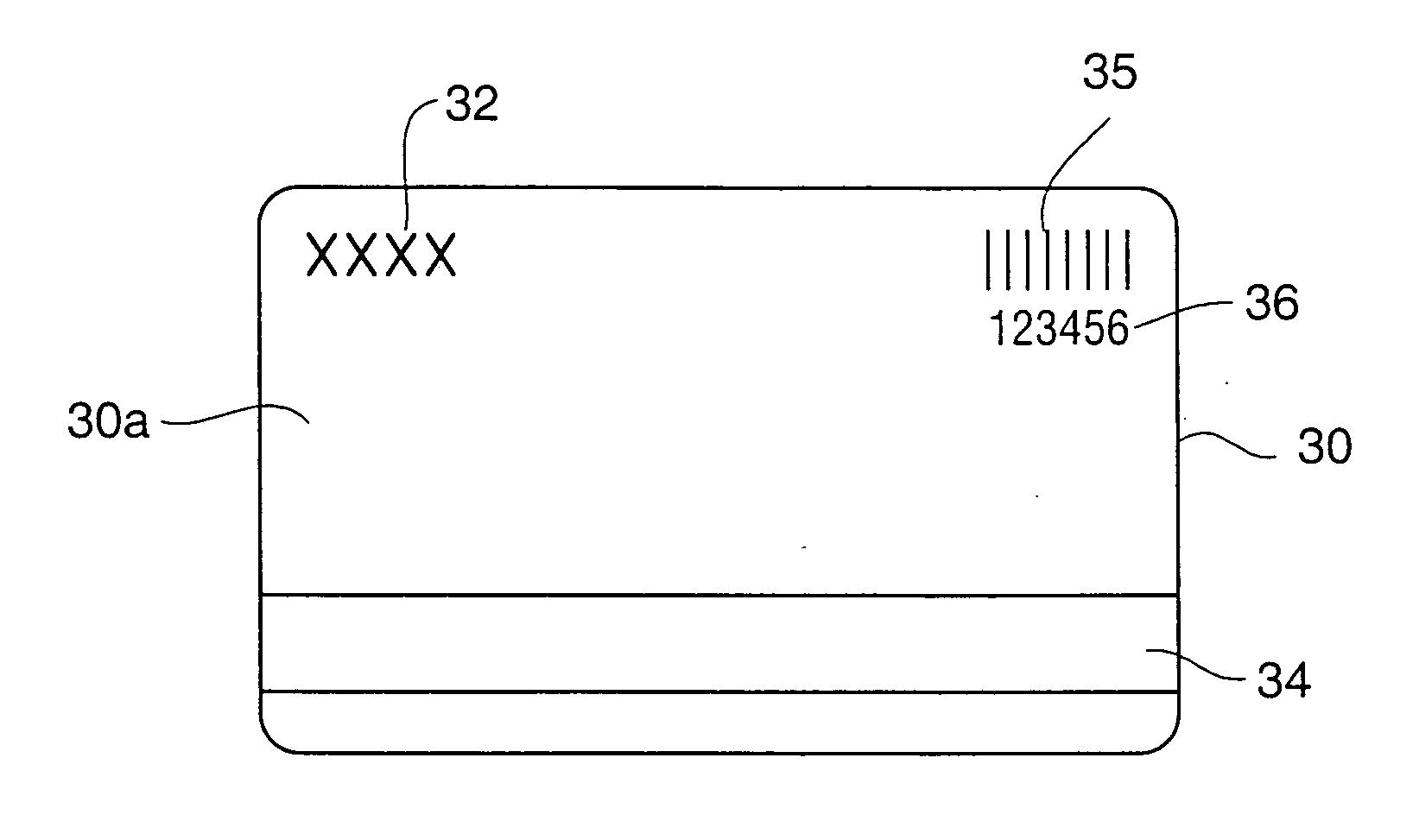
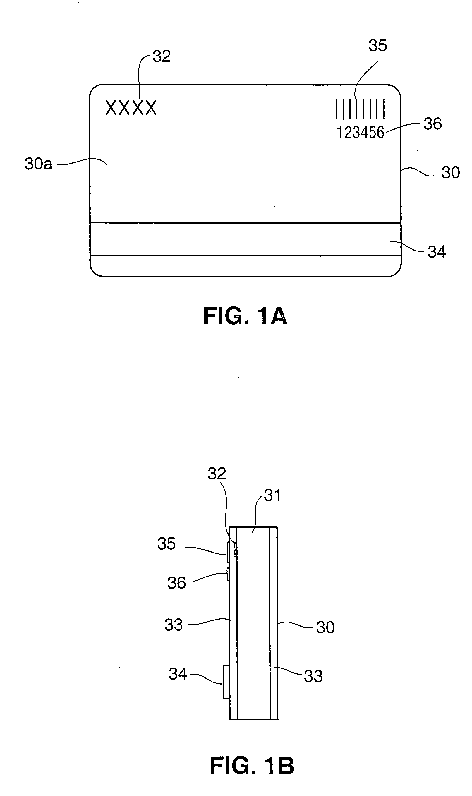
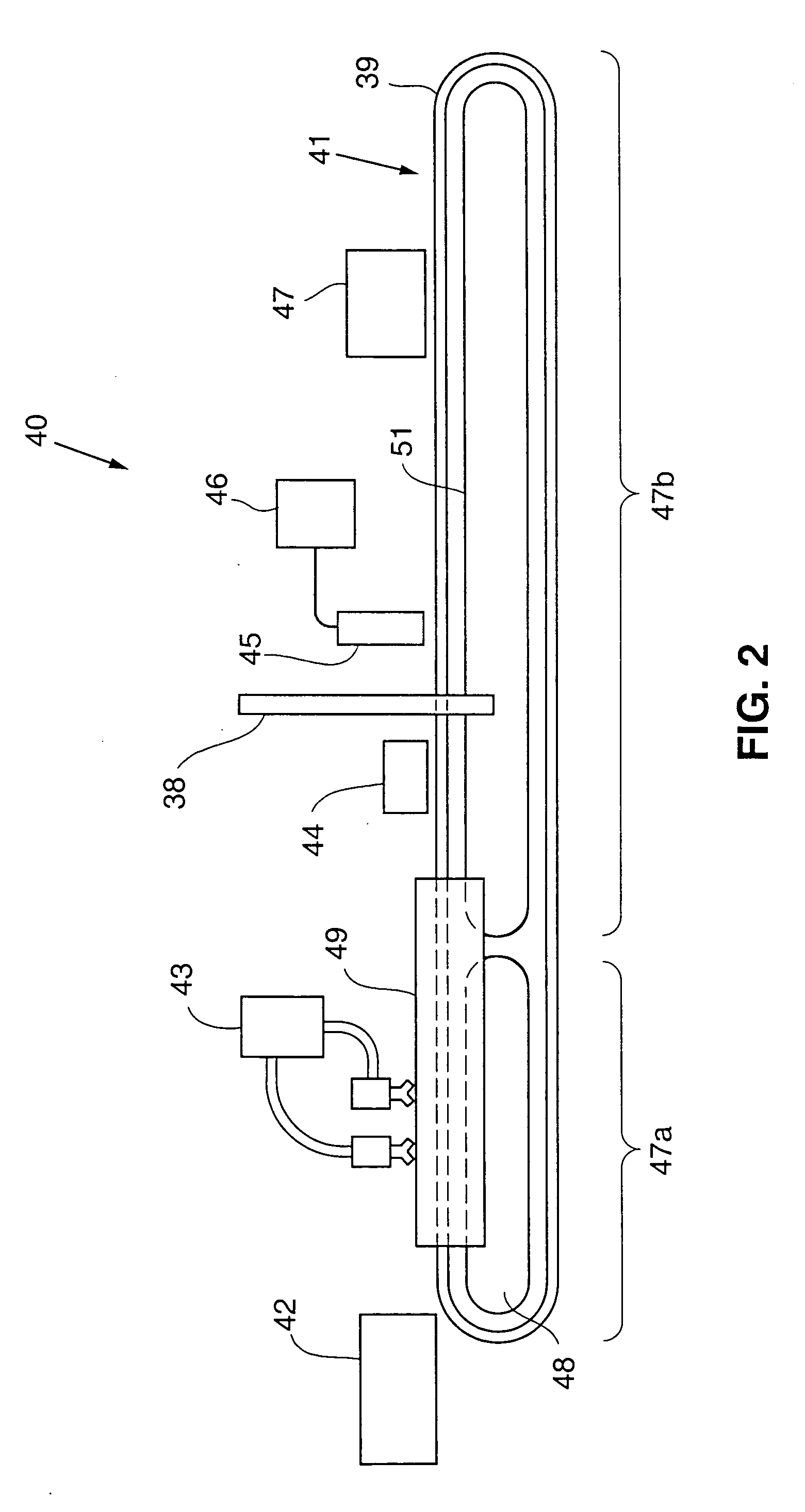
[0025] One embodiment of the invention provides variable imaging where individual items are printed with variable images such as, e.g., identification information or coding (e.g., bar coding). One embodiment provides printing of codes or identification information on transaction cards such as loyalty cards, gift cards, point of sale activated cards. Another embodiment provides printing of sets of individual items such as, e.g., business cards with high durability and / or resolution. According to one embodiment, the printer comprises a conveyor, a treatment stage and a drop on demand ink jet printhead configured to print on an item that has been treated just prior to printing. Where a UV curable or other curable ink is used, the printer further comprises a curing stage. According to one embodiment, the treatment stage comprises a plasma treatment stage where a plasma is applied to the surface of an item to at least temporarily change the surface characteristics of the item. The surface of the item is altered at least just prior to applying the ink to the item. The amount of treatment required is that which is sufficient to create a modified surface in which the ink optimally spreads. The treatment parameters may be variably selected depending on the substrate characteristics, the ink characteristics and the printing technique. The desirable treatment level may depend on the surface tension of the ink with respect to the surface energy of the item. The surface energy in one embodiment is increased to improve ink flow characteristics upon printing, and thereby improve appearance.
[0027] In one embodiment, the invention provides a printed item that has a printed image on a plastic substrate. Such substrates or laminates are typically used where durability of the item is desired, e.g. to prevent staining of the item during storage or use, or to otherwise minimize degradation and enhance product life. Such substrates are thus typically inherently less receptive to inks, particularly inks that may be used in drop on demand printing techniques prior to treating according to the invention. Thus an embodiment of the invention further provides treating a plastic substrate with plasma prior to printing an image on the substrate.
[0029] The present invention further provides an identification tag, such as, e.g., a livestock tracking tag, having improved, durability and image resolution to provide improved barcode or other identification scanning in hostile scanning environments. According to the invention, the printing process and printer described herein may be used to provide a product with reduced problems involving ink migration, ink abrasion, fade resistance and / or ink transfer. While the printed item described in the examples herein comprises a PVC substrate, other substrates including, e.g., Anodized Aluminum, Plated Steel, Polyurethane, Polyester or other suitable polymer and polymer blends may be printed according to the invention.

Problems solved by technology

Livestock identification tags are subjected to high levels of wear.
Production of such items is high in cost particularly since individuated items are necessary.
Requirements for individualization have resulted in a variety of constraints affecting parameters such as printing quality, speed, cost, durability, resolution and materials.
One problem with thermal transfer printing techniques is that the quality of the printing may be compromised by debris on the item.
In addition, this debris can damage the print heads used and cause costly repairs.
Unprinted areas or gaps in printing may be formed, e.g., by damaged printheads or a wrinkled ribbon, and thus the consistency of appearance quality may be compromised.
In addition, the printed image has poor durability; it can be removed through the use of a common, ordinary pencil eraser.
Some of these techniques have been relatively slow and inefficient, requiring costly materials and equipment.
Still other of these printing techniques such as xerography, require special substrate materials to accept the toner from the drum and are not designed for individuated items but rather for sheets of materials.
One disadvantage of continuous ink jet products is that the resolution and durability are not high.
Another disadvantage is that the flight of the droplets is not always consistent resulting in a poor image appearance, e.g., wavy bars in bar codes and text.
This may affect the desired appearance and / or the readability of the coded information in certain applications.
Furthermore, continuous ink jet printing is not economical requiring continuous flow of ink through or into the printhead and thus more ink and fluid.
Continuous ink jet printing also has highly complex equipment with high maintenance costs.
This process uses organic solvent-based inks that become integrated with the surface of the insulation on which they are printed and the process is not used to control flow of droplets over the surface after being applied.
However, one disadvantage to this technique is that because the ink in a printhead is not continuously used, it may dry on face of the printhead leading to poor print quality.
Accordingly, slower drying solvents are used and thus the inks commonly used in drop on demand printing techniques do not dry quickly when applied to a substrate surface.
The slower dry time increases the chances that the ink droplets will spread in an undesirable or uncontrolled manner across the substrate.
The individual droplets of ink will fail to spread sufficiently or will spread too much.
It is believed that dry time in drop on demand printing processes tends to affect appearance negatively at least in part because drop on demand inks are typically less volatile, e.g., than continuous ink jet printing ink, and in using less volatile inks, the dry time tends to allow the printed ink to flow for a longer duration on the substrate, which will alter appearance.
Also, inks used in drop on demand printing tend to sit on the top of the substrate more while continuous ink jet inks attack and penetrate the substrate.
Accordingly, appearance of the printed image using drop on demand printing may be negatively affected.
Additionally, the results of image quality using drop on demand printing can be unpredictable, particularly with relatively less absorbent substrates such as the PVC or other plastic cards that are typically used for individually coded transaction cards.
However, they are typically applied to the substrate and dried or cured in a separate step, which introduces additional manufacturing steps and costs.
Because of their receptivity to inks, coatings and primers tend to attract dirt markings and will lead to a poor appearance over time.
Furthermore, the appearance and image quality of the product may be compromised over time and usage of the product.
In certain products, the printed images may subjected to conditions where the printed image is rubbed or used under physical conditions that cause the image appearance, edge contrast and color density to degrade over time.
All these printing techniques have had other problems including, slow dry time, poor resolution, and poor durability.
Some printing systems such as ink jet systems, thermal transfer printing and dye sublimation have had such poor durability that they require an additional coating or clear layer on top of the printing to protect the printed image.
Furthermore, printing individuated items consistently has had various challenges and problems.
Numbering is done with several slow, labor-intensive, and costly processes.
These processes are slow and have a difficult time reproducing easy-to-read barcodes.
Inkjet printing is a faster process but the ink is not believed to be durable enough for the application and thus is believed to require a separate step to apply a protective coating.
Some of these processes, in particular mechanical stamping and de-bossing are mechanical and therefore are difficult and expensive to use to create variable or individualized identification images or symbology such as barcodes.
In addition, continuous inkjet inks as currently formulated and printed onto a substrate, can fade from sunlight, smear from abrasion, and experience blurring of images due to ink migration on the substrates.
These factors coupled with continuous inkjet printing systems have limited resolution, which reduces the readability of bar codes and make the tag difficult to use for livestock tracking.
Continuous inkjet inks also have problems adhering to certain substrates.
One of the problems with this particular form of identification is the environment in which this process is used.
Dirt, scratches, or manure are just a few of the variables that do not allow for a clean read in the environment in which this barcode is used.
Subsequently, the barcode reader would either not read the barcode information at all or worse, read the number incorrectly, which creates misinformation on the livestock in question.
Due to these problems, Livestock owners are skeptical to participate in a program that is with inherent problems and could misinform on the status of individual livestock.
However, these applications have not been optimal because of the difficulty in providing durable and / or high resolution, readable images, particularly in individualized products with infrared readable printing and even more particularly in a hostile environment such as with livestock where dirt, fading and wear are significant issues in reading or scanning the image.

Method used


Image

  • High durability printed livestock tag and tracking system
  • High durability printed livestock tag and tracking system
  • High durability printed livestock tag and tracking system

Examples


example i

[0072] A Taber Test was performed on cards having bar codes printed according to various printing techniques (“Bar Abrasion Test”). The bar code on four cards of each type were abraded with a Taber Abrasor using dual CS10F abrasion wheels and 500 gram loads on each wheel. After each 50 cycle increment, the bar code was analyzed for edge contrast using a PCS Bar Code Verifier equipped with a visible light wand. The Taber abrasion wheels were re-surfaced for 50 cycles every 250 cycles of usage. The edge contrast was determined using ANSI specification, ANSI X3.182-1990 Bar Code Print Quality Guideline. Edge Contrast can be defined as the difference between bar reflectance (Rb) and space reflectance (Rs) of two adjacent elements, where each transition from a bar to a space or back again is an “edge”. Edge contrast is defined as the difference in peak values in the space (Rs) and that bar (Rb). Each edge in the scan profile is measured, and the edge that has the minimum contrast from th...

example ii

[0074] A Taber Test was performed on cards having a solid black colored bar printed on cards using the three different techniques A-C described above. The solid black color bar on six cards of each type were abraded with a Taber Abrasor using dual CS10F abrasion wheels and 500 gram loads on each wheel. After each 50 cycle increment, the black bar was tested for color density using a MacBeth model TR927 reflection color densitometer. The Taber abrasion wheels were resurfaced for 50 cycles every 250 cycles of usage. The average color (black) density from the six cards of each type, after each measurement is plotted in FIG. 11 and is set forth in Table II below.

TABLE IIBar AbrasionAfterAfterAfterAfterAfterAfterAfterAfterAfterAfter50100150200250300350400450500CardBeforeTaberTaberTaberTaberTaberTaberTaberTaberTaberTaberTypeDensityDensityDensityDensityDensityDensityDensityDensityDensityDensityDensity1A1.571.511.411.351.291.211.181.071.080.990.90B1.571.491.491.361.271.241.141.081.050.990...

example iii

[0077] In order to further assess durability, the ability of a printed bar code to resist exposure to acetone was tested. The following protocol was used to evaluate the solvent resistance of printing on the cards.

[0078] A small amount of Acetone was poured into a glass beaker. A test substrate was provided with a barcode (code 128 or comparable) with ink or other printing material. The printed substrate was wiped with a clean, lint-free cloth. The edge contrast and readability of the bar code(s) was determined with a bar code scanner capable of determining edge contrast and code readability. The cotton portion of a cotton tipped, or equivalent swab was immersed into the solvent for 3 seconds or until it is saturated with the test solvent. With light to medium pressure, the saturated swab was wiped in one direction perpendicular to the lines of the bar code, across the center of the printed area of the substrate 20 times (20 “rub strokes”). The edge contrast and readability of the ...


PUM

PropertyMeasurementUnit
pressureaaaaaaaaaa
thickaaaaaaaaaa
thickaaaaaaaaaa

Abstract

An identification system such as a system used to identify livestock and track ongoing livestock activities or data is provided.

Description

RELATED APPLICATION DATA [0001] This application claims priority of PCT Application No. PCT U.S. 2004 / 001253 and is a continuation in part of U.S. application Ser. No. 10 / 342,908 filed Jan. 15, 2003.FIELD OF THE INVENTION [0002] The invention relates to an identification device, and especially a livestock tag with a relatively high durability, resolution, appearance, and consistency of image quality. BACKGROUND OF THE INVENTION [0003] Livestock tracking has become more import with the spread of livestock diseases such as, mad cow disease. Livestock identification tags are subjected to high levels of wear. Many livestock tags have identification indicia deformed into the substrate. Production of such items is high in cost particularly since individuated items are necessary. [0004] More recently, individualized printed products or individualized sets of product have become desirable, such as, for example, individualized cards such as credit cards, gift cards, loyalty cards, membership...

Claims


Application Information

Patent Timeline
Patent Type & Authority Applications(United States)
IPC IPC(8): B42D15/00B41J3/407B41J11/00B41J13/12
CPCB41J3/407B41J13/12B41J11/002B41J11/0015B41M5/0011B41M5/0047B41M5/0064B41J11/00214
Inventor SCHMITT, STEPHEN E.PETERSON, CHRISROSLAND, MARK
Owner INTECH DIRECT
Why Eureka
Eureka Blog
Learn More