Optical image measuring apparatus and optical image measuring method

Inactive Publication Date: 2006-02-09
KK TOPCON
View PDF4 Cites 26 Cited by
  • Summary
  • Abstract
  • Description
  • Claims
  • Application Information

AI Technical Summary

Benefits of technology

[0041] According to the present invention, the light beam whose intensity is periodically modulated is outputted. The signal light and the reference light in which the polarization characteristics thereof are different from each other are obtained from the light beam and superimposed on each other to produce the first interference light. The plurality of different polarized light components extracted from the first interference light are detected. The signal intensity or the phase of the first interference light is calculated based on the result obtained by detection to form the image of the object to be measured. As a result, as compared with a conventional case, it is unnecessary to provide a light cutoff device (such as particularly a transmission type high-speed shutte

Problems solved by technology

Therefore, the measurement of the object to be measured 105 requires a long time.
In addition, it is hard to shorten a measurement time in view of measurement fundamentals.
Therefore, it is supposedly hard to actually use the apparatus in fields that require a high resolution image, such as a medical field and an industrial field.
Therefore, an apparatus structure and control are complicated and it is likely to increase a cost.
When a transmission type shutter such as a liquid crystal shutter is u

Method used


Image

  • Optical image measuring apparatus and optical image measuring method
  • Optical image measuring apparatus and optical image measuring method
  • Optical image measuring apparatus and optical image measuring method

Examples


first embodiment

[Structure of Apparatus]

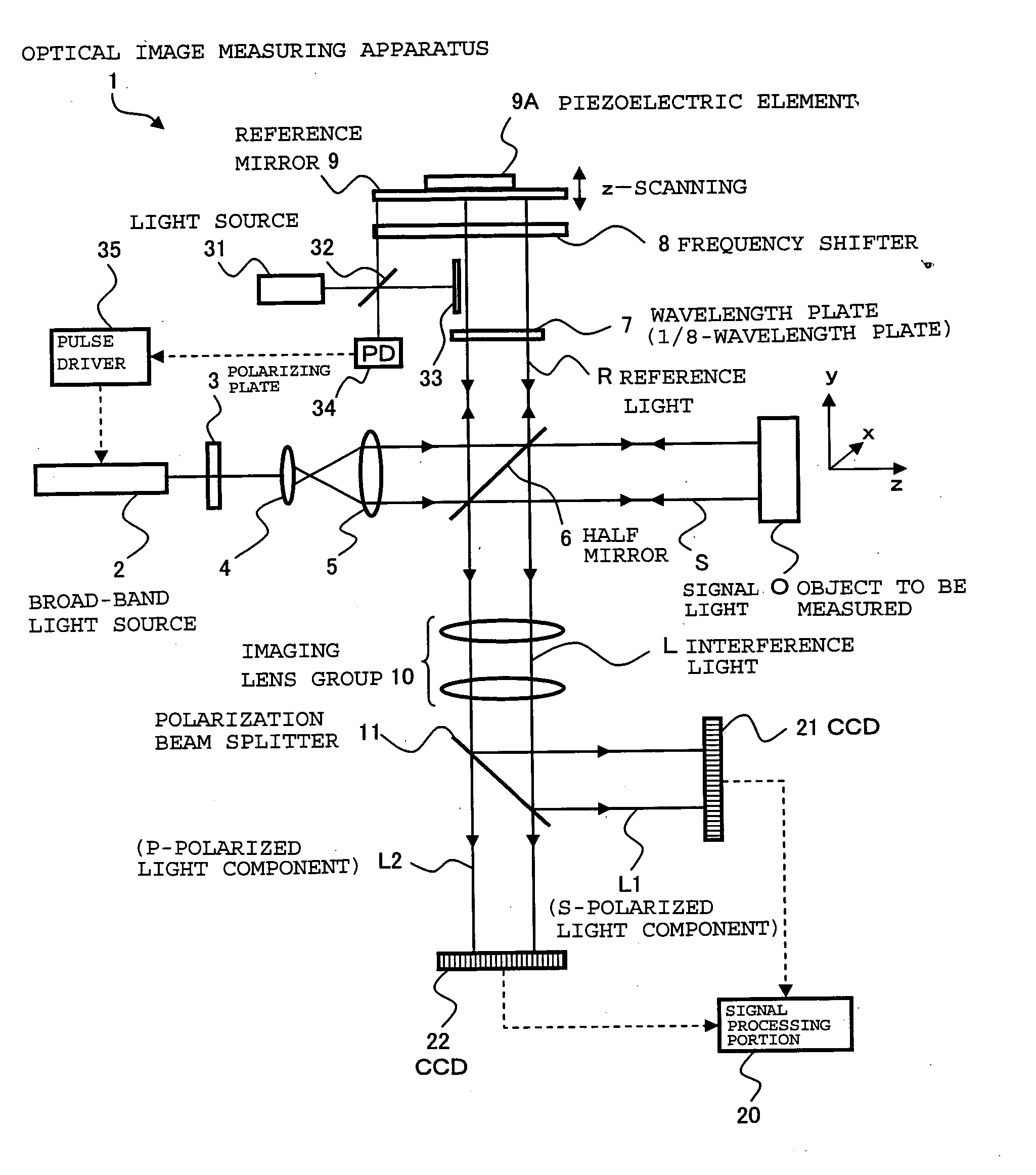
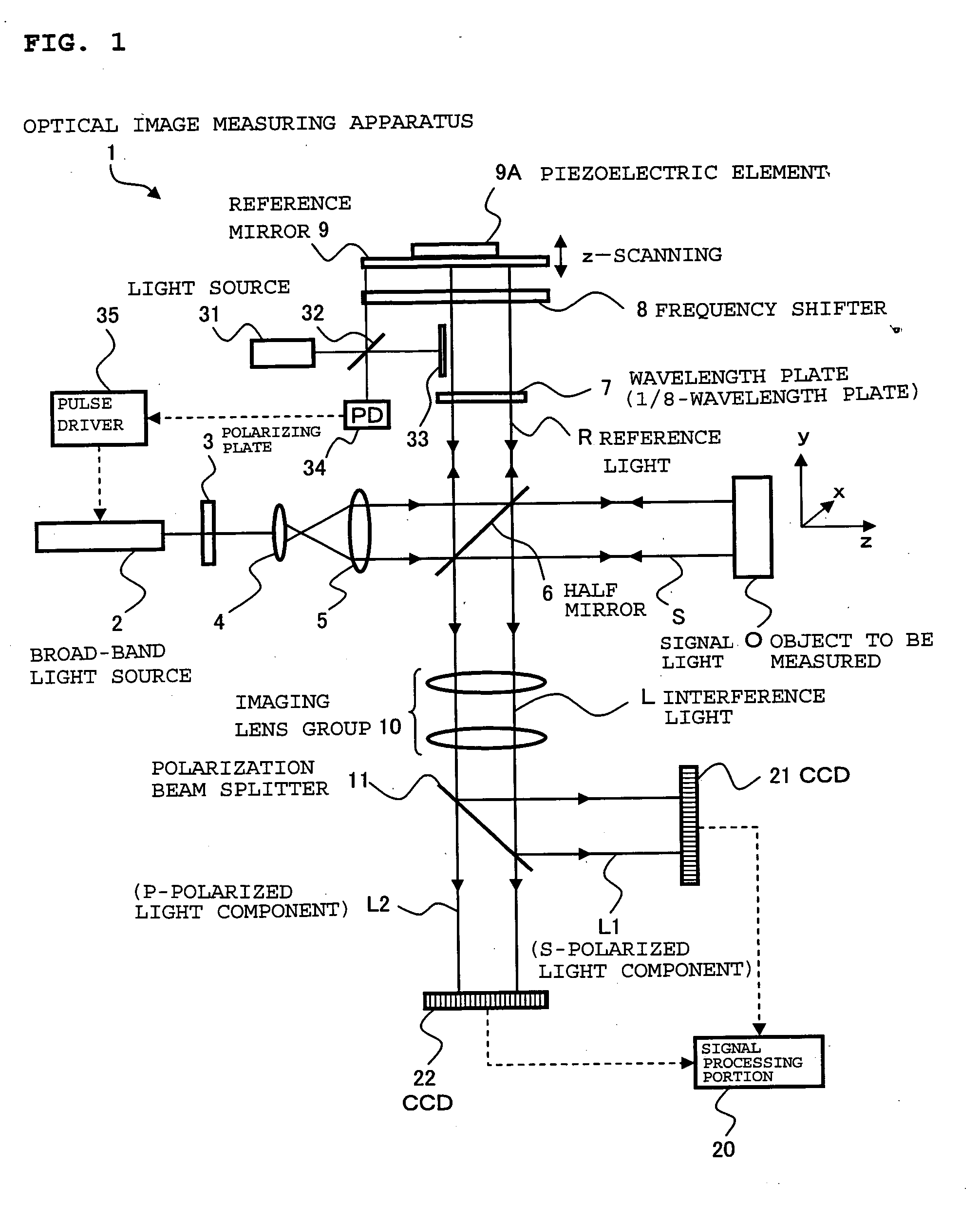
[0051]FIG. 1 shows a schematic structure of an optical image measuring apparatus 1 according to a first embodiment of the present invention. The optical image measuring apparatus 1 is an apparatus available to measure a sectional image and a surface image of an object to be measured O, for example, in the medical field and the industrial field. The object to be measured O is an object which is made of a scattering medium such as a human eye, for example, in the medical field.

[0052] The optical image measuring apparatus 1 includes a broad-band light source 2 for outputting a low-coherent light beam, a polarizing plate 3 for converting a polarization characteristic of the light beam to linear polarization, lenses 4 and 5 for converting the light beam to a parallel light flux and increasing a beam diameter thereof, and a half mirror 6 for dividing the light beam into signal light S and reference light R and also superimposing the signal light S and the referen...

second embodiment

[0117] In the first embodiment described above, the frequency shifter 8 for applying optoelectronic frequency shift or acoustooptic frequency shift and the reference mirror 9 and the piezoelectric element 9A which are for applying Doppler frequency shift are used to shift the frequency of the reference light R. In contrast to this, in this embodiment, the frequency shift is provided only by the frequency shifter 8. The reference mirror 9 and the piezoelectric element 9A are used not for the application of Doppler frequency shift to the reference light R but for scanning of the object to be measured O in the depth direction (z-scanning).

[0118]FIG. 4 shows a schematic structure of an optical image measuring apparatus 1′ according to a second embodiment of the present invention. The optical image measuring apparatus 1′ has substantially the same structure as that described in the first embodiment and includes a control portion 110 for detecting the amount of frequency shift applied by...


PUM


Abstract

Provided is an optical image measuring apparatus capable of effectively obtaining a signal intensity of interference light and phase information thereof by improving detection sensitivity. The optical image measuring apparatus includes a broad-band light source for outputting a light beam whose intensity is periodically modulated, a polarizing plate for converting the light beam to linearly polarized light, a half mirror for dividing the light beam into signal light and reference light and superimposing the signal light and the reference light on each other to produce interference light, a wavelength plate for converting the reference light to circularly polarized light, a frequency shifter for shifting a frequency of the reference light, a reference mirror which is moved by a piezoelectric element, a polarization beam splitter for extracting an S-polarized light component and a P-polarized light component from the interference light, CCDs for detecting the respective polarized light components and outputting detection signals, and a signal processing portion for calculating a signal intensity of the interference light and a phase thereof based on the detection signals. An image of an object to be measured is formed based on a result obtained by calculation.

Description

BACKGROUND OF THE INVENTION [0001] 1. Field of the Invention [0002] The present invention relates to an optical image measuring apparatus that applies a light beam to an object to be measured, particularly a light scattering medium, and produces a surface form or inner form of the object to be measured by detecting a reflected light beam or a transmitted light beam. In particular, the present invention relates to an optical image measuring apparatus for measuring the surface form or inner form of the object to be measured by using an optical heterodyne detection method to produce the image of the measured form. [0003] 2. Description of the Related Art [0004] In recent years, attention has been given to optical imaging technique that produces an image of a surface or inner portion of an object to be measured using a laser light source or the like. This optical imaging technique is not hazardous to human bodies in contrast to the conventional X-ray CT. Therefore, the development of ap...

Claims


Application Information

Patent Timeline
IPC IPC(8): G01B9/02
CPCG01B11/2441G01B9/02003G01B9/02027G01B2290/45G01B9/02014G01B9/02069G01B2290/70G01B9/02091
Inventor CHAN, KINPUIAKIBA, MASAHIRO
Owner KK TOPCON
Why Eureka
Try Eureka