
Process of making two-stage injection stretch blow molded polypropylene articles

a technology of blow molding and polypropylene, which is applied in the direction of other domestic articles, synthetic resin layered products, manufacturing tools, etc., can solve the problems of large size and compactness, large volume of polypropylene, and insignificant replacement of polypropylen

Inactive Publication Date: 2006-02-16
BATLAW RAJNISH +6
View PDF9 Cites 14 Cited by
  • Summary
  • Abstract
  • Description
  • Claims
  • Application Information

AI Technical Summary

Benefits of technology

"The patent text describes a process for making polypropylene containers using a two-stage injection stretch blow molding process. This process involves first forming a preform and then cooling it to ambient temperature before reheating it and expanding it in a mold to form the final container. The invention aims to reduce the cycle time for preform production by reducing the thickness of the preform and using a faster injection rate, which can lead to clearer containers. The technical effect of this invention is to provide a more efficient and cost-effective method for producing polypropylene containers on existing PET manufacturing equipment."

Problems solved by technology

The explanation for this is that the shipping costs for fully blown containers are significantly greater than shipping costs for preforms, which are much smaller and more compact.
However, polypropylene has not significantly replaced PET as the material of choice for drink bottle manufacturing.
One reason that polypropylene has not replaced PET as the material of choice, given its lower overall raw material costs, is that the injection and blow molding cycle time for polypropylene has been excessively long.
The long cycle time for preform and bottle production drives up the cost for using polypropylene as compared to PET for container manufacture.
Productivity for polypropylene preform production in conventional processes is low in part because of the undesirably high preform thickness and the use of thermal gates.
It has been mainly the long cooling time that has caused the cycle time for polypropylene preforms to be cost prohibitive.
Using a relatively fast injection rate (could still be a short cycle-time) for thin walled preforms unexpectedly can lead to bottles having low clarity.
High injection rates in conventional prior art preform manufacture sometimes have adversely affected the orientation of the crystal structure in the preform, which induces undesirable haze in the final container.
Currently known methods of injection stretch blow molding PET preforms have generally not been successfully employed for polypropylene container manufacture.
However, thick preform walls reduce the processing speeds that can be achieved.
Thick-walled preforms must be cooled longer before removal from a preform mold, thus undesirably increasing processing time in preform manufacture.
The injection rate for production of preforms, however, is relatively slow.
However, this patent disclosure teaches the use of a melt flow index that is relatively low, resulting in a relatively viscous polypropylene resin.
Viscous resins are not easily adapted to rapid injection rates in the manufacture of preforms.
This reduces overall productivity and manufacturing efficiency.
It is believed that the process cannot reliably form polypropylene containers at a container production rate of more than about 900 containers per cavity per hour.
Until the development of this invention, many attempts to injection stretch blow mold polypropylene have been commercially undesirable.
This has been believed to be due in part to a relatively slow production speed for such polypropylene articles at acceptable container haze levels.
A disadvantage of polypropylene containers has been the inability to make containers of high clarity (i.e. low haze) at a high rate of speed.
However, conventional methods for making polypropylene containers having such low levels of haze have been relatively slow.
Slow processes are not economically viable in the marketplace.
It is a significant and difficult challenge to develop a process that will facilitate increased stretch molding speed while not sacrificing clarity of the resulting container.

Method used


Image

  • Process of making two-stage injection stretch blow molded polypropylene articles
  • Process of making two-stage injection stretch blow molded polypropylene articles
  • Process of making two-stage injection stretch blow molded polypropylene articles

Examples


example 1

38 mm Neck, 4 mm Wall Preforms

[0098] Commercial random copolymer resins containing Millad 3988 (Borealis) were used to produce preforms as indicated in Table I. The preforms were produced on a two-cavity mold (only one cavity installed) 100 ton Netstal injection molding machine with a variable injection time (0.5-4.0 sec) and a constant cooling time of 22 sec. Melt temperature was 230° C. Temperature of the cooling water was 13° C. The holding pressure time was 9.2 sec. Total cycle time was around 37 sec (not optimized). A valve gate with a diameter of 1.5 mm was used. The preforms have a wall thickness of 4 mm and a bottle weight of about 25.3 g. These preforms were later blown into bottles as explained in subsequent examples.

TABLE IExample 1 PreformsInjectionInjectionMFITimeSpeedExampleResin(g / 10 sec)(sec)(g / cc)I-1RB307MO1.50.550.6I-2RB307MO1.51.025.3I-3RB307MO1.51.516.9I-4RB307MO1.52.012.7I-5RB307MO1.52.510.1I-6RB307MO1.53.08.4I-7RB307MO1.53.57.2I-8RB307MO1.54.06.3I-9RE420MO13...

example 2

38 mm Neck, 3 mm Wall Preforms

[0099] Commercial random copolymer resins containing Millad 3988 (Borealis) were used to produce preforms as indicated in Table II. The preforms were produced on a two-cavity mold (only one cavity installed) 100 ton Netstal injection molding machine with a variable injection time (0.54.0 sec) and a constant cooling time of 10 sec. Melt temperature was 230° C. Temperature of the cooling water was 13° C. The holding pressure time was 4.5 sec. Total cycle time was around 20 sec (not optimized). A valve gate with a diameter of 1.5 mm was used. The preforms have a wall thickness of 3 mm and a bottle weight of about 20.3 g. These preforms were later blown into bottles as explained in subsequent examples.

TABLE IIExample 2 PreformsInjectionInjectionMFITimeSpeedExampleResin(g / 10 sec)(sec)(g / cc)II-1RB307MO1.50.540.6II-2RB307MO1.51.020.3II-3RB307MO1.51.513.5II-4RB307MO1.52.010.2II-5RB307MO1.52.58.1II-6RB307MO1.53.06.8II-7RB307MO1.53.55.8II-8RB307MO1.54.05.1II-9...

example 3

38 mm Neck, 2 mm Wall Preforms

[0100] Commercial random copolymer resins containing Millad 3988 (Borealis) were used to produce preforms as indicated in Table 11. The preforms were produced on a two-cavity mold (only one cavity installed) 100 ton Netstal injection molding machine with a variable injection time (0.54.0 sec) and a constant cooling time of 10 sec. Melt temperature was 230° C. Temperature of the cooling water was 13° C. The holding pressure time was 2 sec. Total cycle time was around 20 sec (not optimized). A valve gate with a diameter of 1.5 mm was used. The preforms have a wall thickness of 2 mm and a bottle weight of about 17.3 g. These preforms were later blown into bottles as explained in subsequent examples.

TABLE IIIExample 3 PreformsInjectionInjectionMFITimeSpeedExampleResin(g / 10 sec)(sec)(g / cc)III-1RB307MO1.50.534.6III-2RB307MO1.51.017.3III-3RB307MO1.51.511.5III-4RB307MO1.52.010.2III-5RB307MO1.52.56.9III-6RB307MO1.53.05.8III-7RB307MO1.53.54.9III-8RB307MO1.54.0...


PUM

PropertyMeasurementUnit
thicknessaaaaaaaaaa
thicknessaaaaaaaaaa
diameteraaaaaaaaaa

Abstract

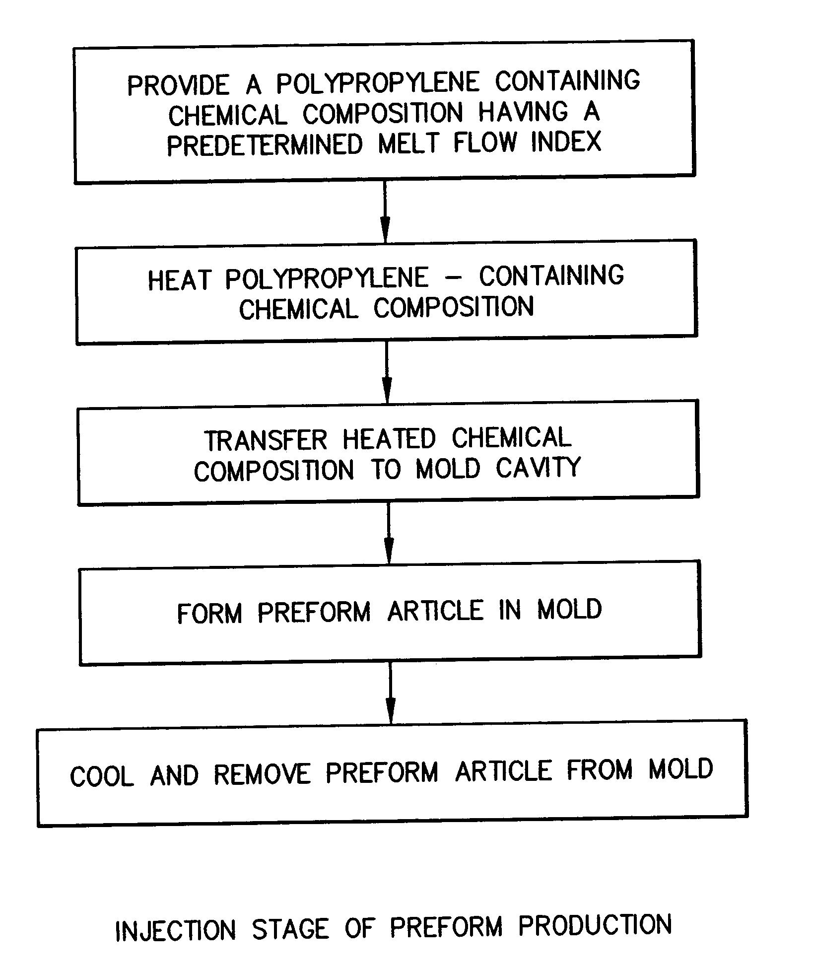
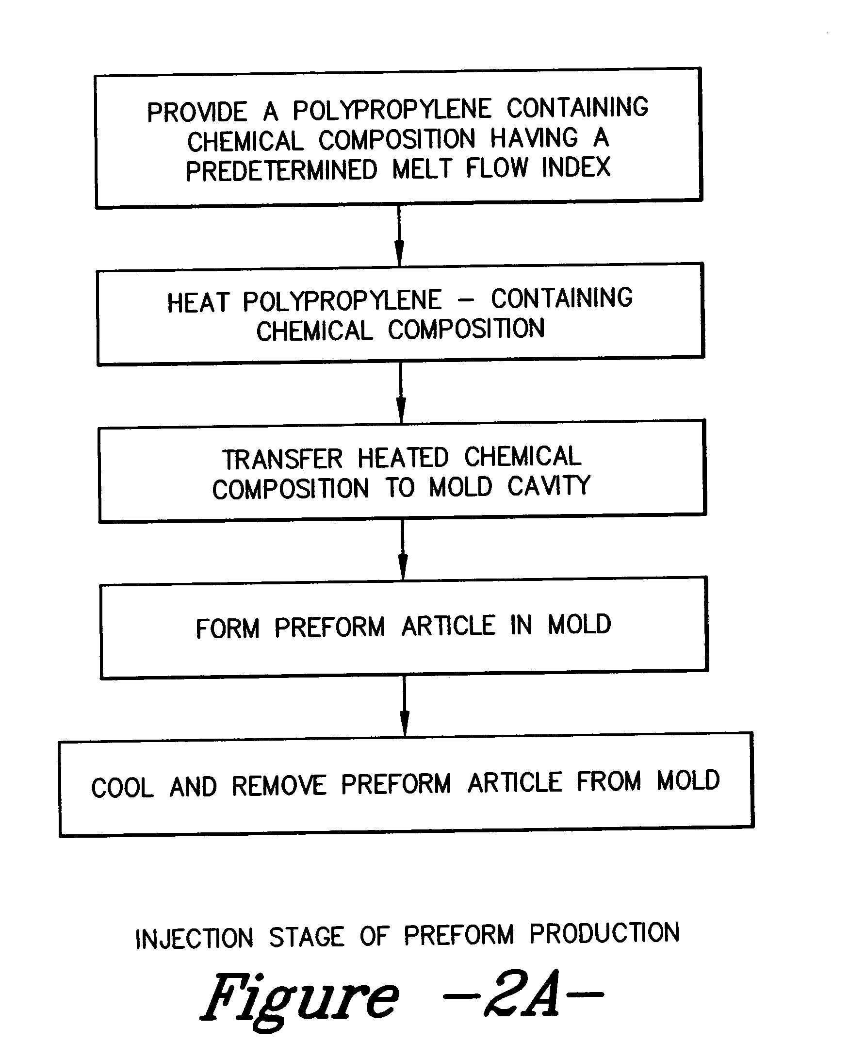
The two stage production of clear, low-haze, injection stretch blow molded polypropylene container articles is disclosed. In the first processing stage, a preform article is manufactured on an injection molding machine. In a second and subsequent step, which may occur remotely from apparatus used in the first step, the preform article is heated and stretch blown into a container. The process may employ the selection of processing parameters to produce preform articles that facilitate stretch blow molding at relatively high rates of speed, while still maintaining an appropriate polypropylene polymer morphology that results in clear, low haze containers.

Description

CROSS REFERENCE TO RELATED APPLICATION [0001] This application is a divisional application of U.S. Ser. No. 10 / 764,234 (5729) filed on Jan. 23, 204, currently pending.FIELD OF THE INVENTION [0002] This invention relates to production of two-stage injection stretch blow molded polypropylene articles. BACKGROUND OF THE INVENTION [0003] Injection stretch blow molding is a process of producing thermoplastic articles, such as liquid containers. This process involves the initial production of a preform article by injection molding. Then, the preform article that after reheating is subjected to stretching and gas pressure to expand (blow) the preform article against a mold surface to form a container. [0004] There are several different processes that employ stretch blow molding. A first type is a single stage process in which a preform is made on a machine and allowed to cool somewhat to a predetermined blow molding temperature. While still at this elevated temperature, the preform is stre...

Claims


Application Information

Patent Timeline
Patent Type & Authority Applications(United States)
IPC IPC(8): B29C49/06B29C49/08B29C49/64B32B27/08B29B11/08B29B11/14B29C45/00B29C49/00B29C49/12B29C49/18B29C49/36
CPCB29B11/08Y10T428/1352B29B2911/1402B29B2911/14026B29B2911/14033B29B2911/1404B29B2911/14106B29B2911/14133B29B2911/14593B29B2911/14726B29B2911/14906B29B2911/1498B29C45/0001B29C49/0005B29C49/06B29C49/12B29C49/18B29C49/36B29K2023/00B29K2023/086B29K2023/12B29K2623/12B29B11/14B29C2949/3024B29C2949/28B29C2949/26B29C2949/24B29C2949/22B29C2949/3032B29C2949/0811B29C2949/0831B29C2949/0862B29C2949/0872B29C49/071B29C2949/0715B29C49/42394
Inventor BATLAW, RAJNISHBURKHART, BRIANVERMEERSCH, BERNARDVAN HOECKE, PEDRODELAERE, MARCPEDROZA, ROBERTO GUZMANKURJA, JENCI
Owner BATLAW RAJNISH
Learn More