Cogeneration system

a cogeneration system and energy efficiency technology, applied in the field of cogeneration systems, can solve the problems of limited enhancement of system efficiency, inefficient re-use of generator waste heat, and increase of noise, so as to prevent the frosting of outdoor heat exchangers, and enhance the energy efficiency of cogeneration system

Inactive Publication Date: 2006-02-23
LG ELECTRONICS INC
View PDF0 Cites 13 Cited by
  • Summary
  • Abstract
  • Description
  • Claims
  • Application Information

AI Technical Summary

Benefits of technology

[0021] The cogeneration system according to the present invention has an advantage in that waste heat of the generator is supplied to the heat consumer, so that it is possible to enhance the energy efficiency of the cogeneration system and to release heat from the generator.
[0022] The cogeneration system according to the present invention also has an advantage in that waste heat of the generator and waste heat of the engine are supplied to the heat consumer, so that it is possible to enhance the energy efficiency of the cogeneration system.
[0023] Also, the cogeneration system according to the present invention has an advantage in that it is possible to prevent the outdoor heat exchanger from being frosted, using waste heat of cooling water of the engine and waste heat of the generator, and to enhance the heating performance of the indoor heat exchanger, using waste heat of exhaust gas of the engine.
[0024] In addition, the cogeneration system according to the present invention has an advantage in that waste heat of exhaust gas is used to defrost the outdoor heat exchanger when outdoor temperature corresponds to a temperature, at which the outdoor heat exchanger may be easily frosted, and the waste heat of the exhaust gas is used to enhance the heating performance of the indoor heat exchanger when the outdoor temperature does not correspond to the easy-frost temperature, so that the cogeneration system can positively cope with the outdoor temperature while exhibiting a high energy efficiency.

Problems solved by technology

However, such a conventional cogeneration system has problems of an increase in noise occurring during operation of the cooling fan, inefficient re-use of waste heat of the generator, and limited enhancement in the efficiency of the system.

Method used


Image

  • Cogeneration system
  • Cogeneration system
  • Cogeneration system

Examples


first embodiment

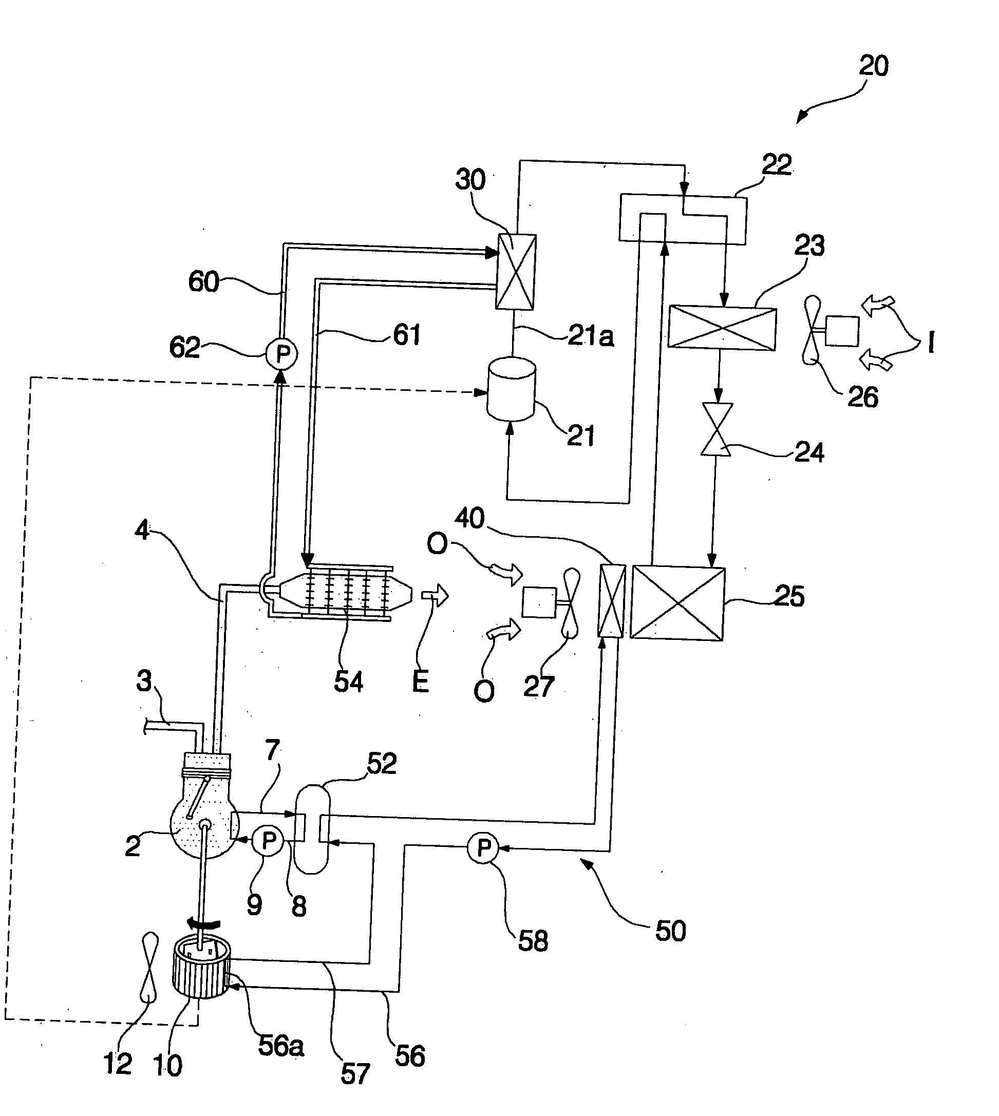
[0036]FIG. 1 is a schematic diagram of a cogeneration system according to the present invention.

[0037] As shown in FIG. 1, the cogeneration system includes an engine 2, a generator 10 connected to an output shaft of the engine 2 to generate electricity, and a waste heat recovering means 40 to recover waste heat of the generator 10, and to transfer the recovered waste heat to a heat consumer 20.

[0038] The engine 2 includes a combustion chamber defined in the interior of the engine 2.

[0039] A fuel tube 3 and an exhaust tube 4 are connected to the engine 2. The fuel tube 3 is adapted to supply fuel such as liquefied gas or liquefied petroleum gas into the combustion chamber. The exhaust tube 4 is adapted to guide exhaust gas discharged from the combustion chamber.

[0040] The generator 10 may be an AC generator or a DC generator.

[0041] The electricity generated from the generator 10 is used in various electrical devices 11 such as electric lamps and in the heat consumer 20.

[0042] Th...

second embodiment

[0096] The operations of the first and second heat medium circulation pumps 58 and 62, and the enhancement of the heating performance of the indoor heat exchanger 23 and the effect of defrosting the outdoor heat exchanger 25 respectively achieved by those operations are the same as those of the second embodiment, so that no detailed description thereof will be given.

[0097] When the heat pump type air conditioner 20 operates in the cooling mode, the controller 80 controls the control valve 76 to open the exhaust conduit 72 and to close the branched conduit 74.

[0098] In this case, exhaust gas E discharged from the engine 2 is guided to the exhaust gas heat exchanger 54 via the exhaust conduit 72, and is then discharged to the atmosphere after releasing its heat into the exhaust gas heat exchanger 54, as shown in FIG. 6. The exhaust gas heat exchanger 54 releases the heat absorbed from the exhaust gas to the atmosphere.

fourth embodiment

[0099]FIG. 7 is a schematic diagram of a cogeneration system according to the present invention.

[0100] As shown in FIG. 7, the cogeneration system includes a plurality of engines 2, 2′ . . . . The cogeneration system also includes a plurality of generators 10, 10′ . . . connected to respective shafts of the engines 2, 2′ . . . . The cogeneration system of the second embodiment has the same configuration and functions as those of the second and third embodiments, except for the engines 2, 2′ . . . and generators 10, 10′ . . . . Accordingly, the constituent elements of the fourth embodiment respectively corresponding to those of the first and second embodiments are designated by the same reference numerals, and no detailed description thereof will be given.

[0101] One or more of the engines 2, 2′ . . . operate in accordance with the load to be cooled or heated.

[0102] Fuel tubes 3, 3′ . . . and exhaust gas tubes 4, 4′ . . . are connected to respective engines 2, 2′ . . . . Exhaust con...


PUM


Abstract

A cogeneration system including an engine, a generator connected to an output shaft of the engine to generate electricity, and a waste heat recoverer to recover waste heat of the generator and to transfer the recovered waste heat to a heat consumer. Since waste heat of the generator is supplied to the heat consumer, the cogeneration system exhibits a high energy efficiency while achieving release of heat from the generator.

Description

BACKGROUND OF THE INVENTION [0001] 1. Field of the Invention [0002] The present invention relates to a cogeneration system, and, more particularly, to a cogeneration system in which waste heat of a generator is recovered, and is supplied to a heat consumer. [0003] 2. Description of the Related Art [0004] In general, cogeneration systems include an engine, a generator to generate electricity, using a rotating force outputted from the engine, and a heat transfer means to supply waste heat of the engine to a heat consumer such as a water heater or an air conditioner. [0005] Electricity generated from the generator is used to operate electrical devices such as electric lamps. [0006] A cooling fan is equipped in the generator to release heat from the generator. [0007] The heat transfer means recovers waste heat of cooling water used to cool the engine or waste heat of exhaust gas discharged from the engine, and supplies the recovered waste heat to a water heater or an air conditioner. [0...

Claims


Application Information

Patent Timeline
Patent Type & Authority Applications(United States)
IPC IPC(8): F25B27/00F02C6/00F02G1/00B60H1/00
CPCY02E20/14F25B27/02Y02A30/274F02C6/18
Inventor KANG, SEUNG TAKCHOI, CHANG MINCHOI, WON JAELIM, HYUNG SOOHWANG, YOON JEI
Owner LG ELECTRONICS INC
Why Eureka
Try Eureka