
Image forming method and image forming apparatus

Active Publication Date: 2006-02-23
KONICA MINOLTA INC
View PDF2 Cites 0 Cited by
  • Summary
  • Abstract
  • Description
  • Claims
  • Application Information

AI Technical Summary

Benefits of technology

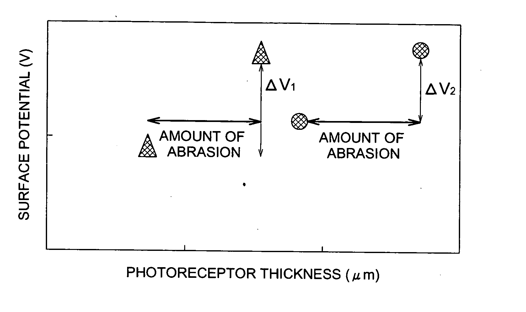
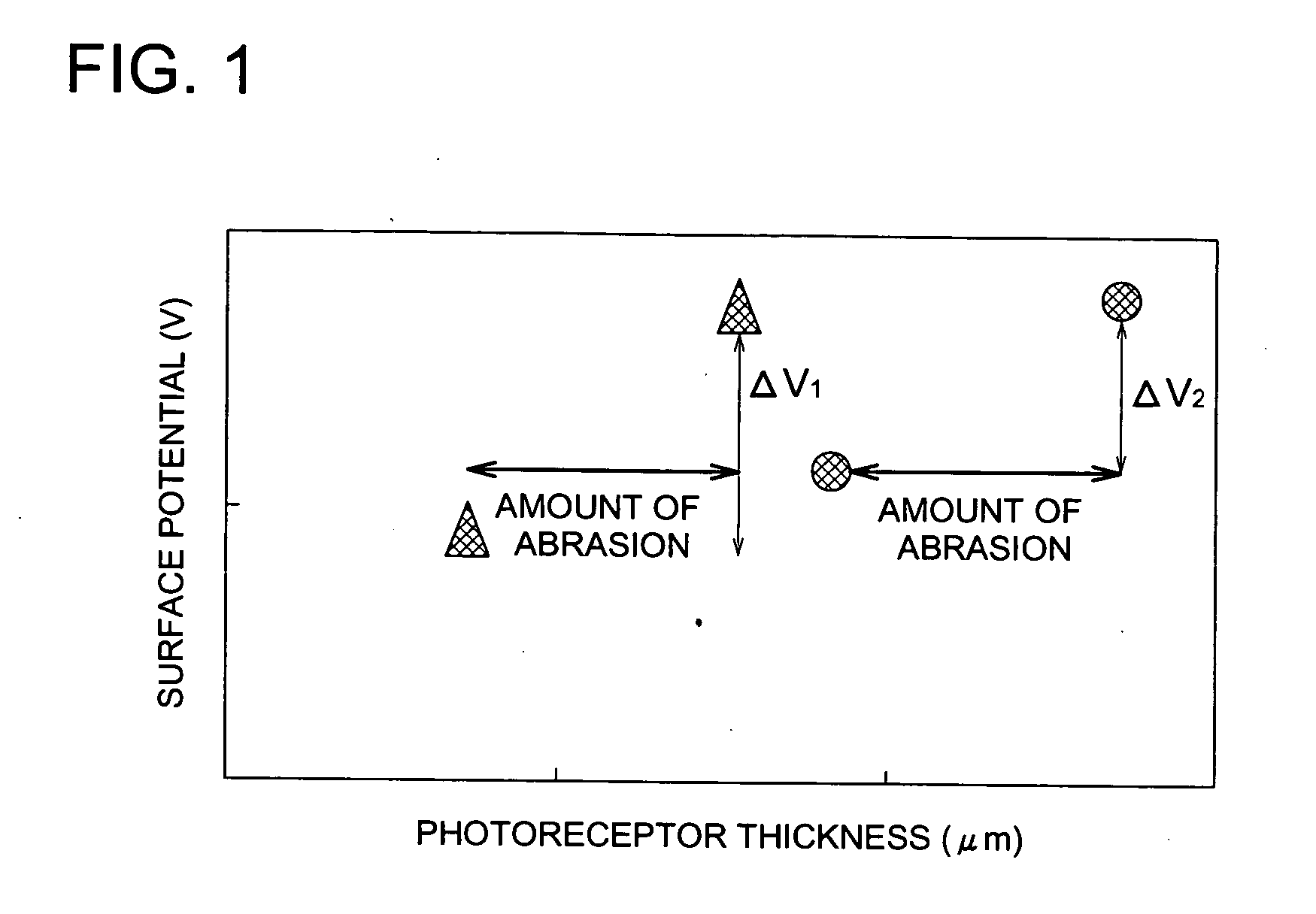
[0022] As a result of continuous study of the aforementioned problem, we have used an organic photoreceptor that has been made thin to improve sharpness, and we have found that in order to prevent the occurrence of image unevenness and mackle caused by abrasion unevenness of the organic photoreceptor, it is effective to use a development method in which, concentrated image unevenness in image density is not allowed to occur even if there is abrasion unevenness on the surface of the organic photoreceptor. The present invention was thereby brought to completion. That is to say, a two-component developing agent with favorable developing properties whose carrier resistivity is within a specified range was used to visualize the electrostatic latent image formed on an organic photoreceptor that has been made thin, and thus image unevenness and mackle was prevented and the present invention was thereby achieved.

Problems solved by technology

However, drawbacks of the organic photoreceptor are that mechanical strength and chemical durability are low, and when multiple sheet printing is done, there is deterioration of the electrostatic characteristics of the photoreceptor, or generation of defects on the photoreceptor surface and the like.
However, in the aforementioned methods in which the charge transfer layer is made thick or a high-strength protective layer is provided, there is the problem that the carrier generated at the charge transfer layer diffuses in the horizontal direction and reaches as far as the surface, and this causes problems with sharpness and the like.
In the digital photocopier field, the demand for higher quality images has been increasing, and high resolution image formation is being researched, but in this type of layer structure or in the protective layer in which carrier diffusion occurs easily, a favorable electrostatic latent image cannot be obtained.
However, in order to do this, it is necessary to limit the diffusion of the carrier generated so that it does not reach the surface charge.
It has been reported that in latent image deterioration of a high density image, when the ratio D / μ of the diffusion constant of the charge transfer layer (D) and the drift mobility (μ) is large, the effect of diffusion to the electrostatic latent image cannot be disregarded, and when the charge transfer layer is thick, latent image deterioration increases (Non-patent Document 1).
However, when these thin organic photoreceptors which have been proposed are actually used in electrophotographic image forming apparatuses, when the image is formed, image unevenness due to uneven mechanical abrasion is more likely to be outstanding.
Furthermore, it is more difficult to maintain image quality over a long period of time when compared with the organic photoreceptor of the prior art that has a thickness of 20 μm or more.
Consequently, when a thin organic photoreceptor is used, image unevenness is likely to occur due to unevenness in abrasion of the organic photoreceptor.
In addition, when a thin organic photoreceptor is used and a developing agent having small particle diameter toner is employed in order to obtain high image quality, at those portions of the organic photoreceptor where abrasion unevenness occurs, mackle is likely to occur.

Method used


Image

  • Image forming method and image forming apparatus
  • Image forming method and image forming apparatus
  • Image forming method and image forming apparatus

Examples


preparation example 1

Toner Preparation Example 1

Example of Emulsification, Polymerization and Association Method

[0239] 0.90 kg of sodium n-dodeycl sulfate was added to 10.0 liters of pure water and dissolved while stirring. 1.20 kg of Regal 300R (carbon black manufactured by Cabot Corporation) was gradually added to the resultant solution. After stirring well for 1 hour, the solution was continuously dispersed for 20 hours using a sand grinder (a medium type disperser). This resultant dispersion was designated as the “fixing agent dispersion 1”.

[0240] In addition, a solution of 0.055 kg of sodium dodecylbenzenesulfonate and 4.0 liters of deionized water was designated the “anion surfactant solution A”.

[0241] A solution of 0.014 kg of nonyl phenol polyethylene oxide 10-mol addition product and 4.0 litres of deionized water was designated as the “nonion surfactant solution B”.

[0242] A solution formed by dissolving 223.8 g of potassium persulfate and 12.0 litres of deionized water was designated as the...


PUM


Abstract

An image forming method, comprising the steps of: charging a organic photoreceptor having a specific layer including at least a photosensitive layer; forming an electrostatic latent image on the organic photoreceptor; developing the electrostatic latent image to form a visible toner image by using a developing agent; transferring the toner images to be superimposed on a toner image receiving member; and removing the toner remaining on the organic photoreceptor, wherein the total thickness of the specific layer in the organic photoreceptor, is 5-15 μm, and wherein the developing agent comprises a toner and a carrier having the volume resistivity of 108-1012 Ω cm.

Description

FIELD OF THE INVENTION [0001] The present invention relates to an image forming method and an image forming apparatus for use in the fields of electrophotographic copy machines and printers. BACKGROUND OF THE INVENTION [0002] In recent years, organic photoreceptors have been widely used in electrophotoreceptors. The organic photoreceptor is advantageous when compared to other photoreceptors because: the material for all types of exposure light sources, from visible light to infrared light, can be easily developed; materials which do not cause environmental pollution can be selected; and manufacturing cost is low. However, drawbacks of the organic photoreceptor are that mechanical strength and chemical durability are low, and when multiple sheet printing is done, there is deterioration of the electrostatic characteristics of the photoreceptor, or generation of defects on the photoreceptor surface and the like. [0003] In other words, because electrical and mechanical external forces m...

Claims


Application Information

Patent Timeline
IPC IPC(8): G03G21/00
CPCG03G9/0823G03G5/043
Inventor YOSHIZAWA, HIDEOYAMAZAKI, HIROSHI
Owner KONICA MINOLTA INC
Learn More