
Vibration isolation system for a vacuum chamber

a vacuum chamber and vibration isolation technology, applied in the direction of machines/engines, positive displacement liquid engines, transportation and packaging, etc., can solve the problems of unbalanced elasticity of the bellows, increase in construction costs, and increase in manufacturing costs, so as to improve the stability of the vacuum chamber

Inactive Publication Date: 2006-03-02
EBARA CORP
View PDF6 Cites 10 Cited by
  • Summary
  • Abstract
  • Description
  • Claims
  • Application Information

AI Technical Summary

Benefits of technology

[0021] The present invention has been made in view of the above drawbacks. It is therefore an object of the present invention to provide a vibration isolation system which can prevent transmission of vibration from a transfer unit or other unit such as a vacuum pump to a vacuum chamber, and can accurately perform positioning of the vacuum chamber connected to an elastic member having a simple structure and a transfer space therein.
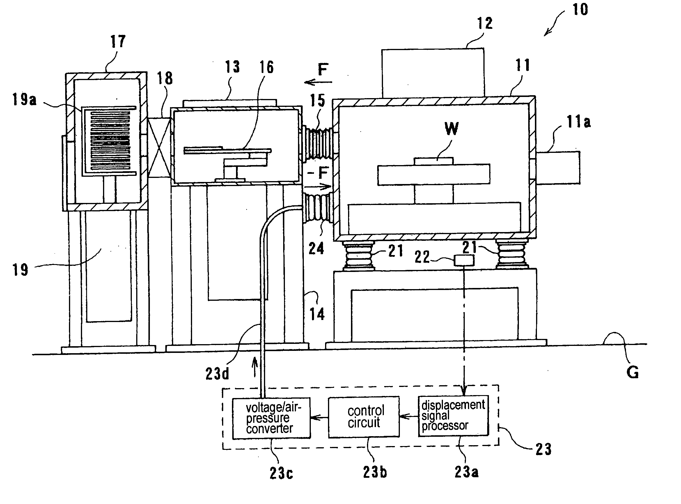
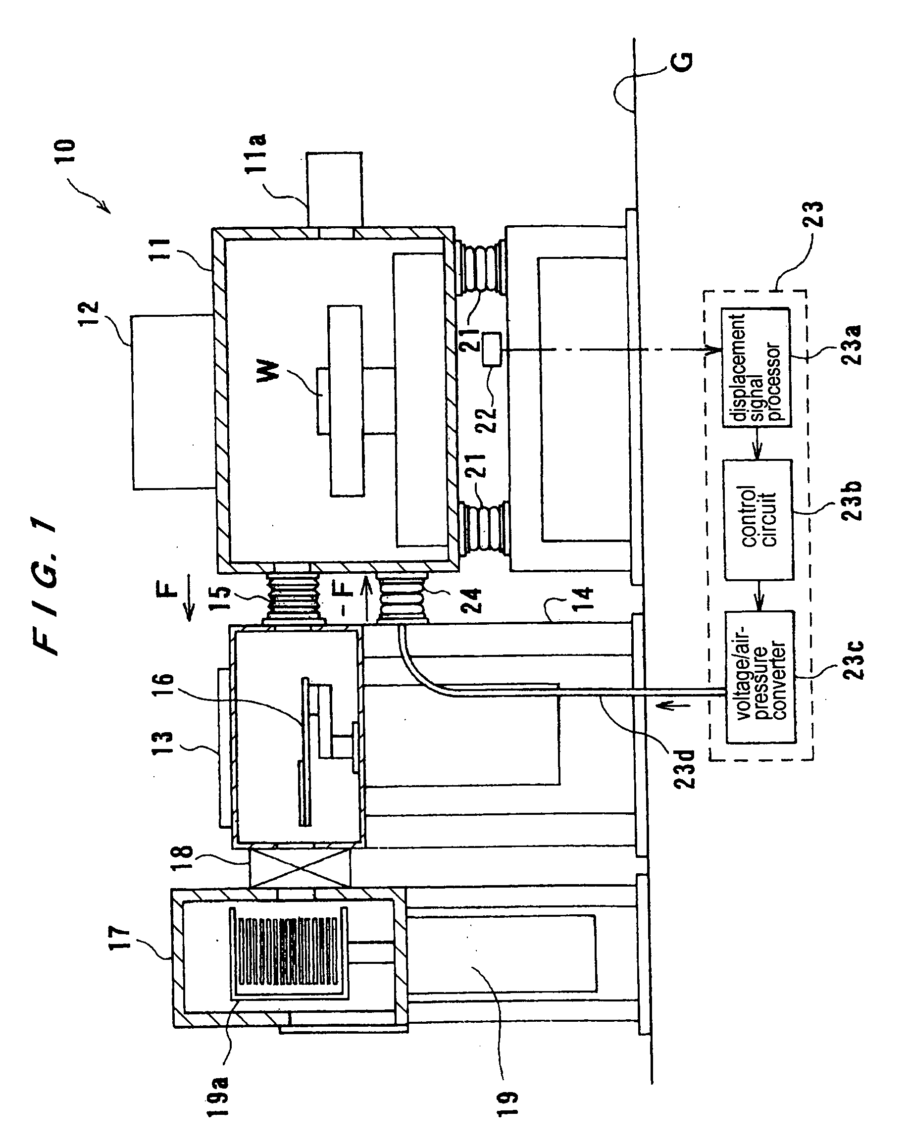
[0023] According to the present invention, while the transfer chamber is fixed to the installation floor, the vacuum chamber is placed on the vibration isolation unit. This system has the elastic member, which has the transfer space therein, for connecting the vacuum chamber and the transfer chamber to each other and the actuator for supporting the vacuum chamber with respect to the fixed member. With this structure, when an attracting force is produced by the evacuation of the vacuum chamber to attract the vacuum chamber to the transfer chamber, the displacement of the vacuum chamber is detected, and then a biasing force, which is adjusted according to the detection information, against the attracting force is applied from the actuator to the vacuum chamber. Therefore, the forces applied to the vacuum chamber are cancelled, and hence the displacement of the vacuum chamber is quickly compensated and the vacuum chamber is thus returned to the original position. In this manner, the accurate positioning of the vacuum chamber with respect to the transfer chamber at the fixed side is performed. Because the vacuum chamber is placed on the vibration isolation unit and is connected to the transfer chamber through the actuator and the elastic member, the vibration from outside can be damped or reduced, and the vibration produced in the vacuum chamber itself can also be damped or reduced.
[0024] In the present invention, the control unit controls the actuator so as to keep the position of the vacuum chamber constant even when the pressure in the vacuum chamber is changed. It is preferable to provide a plurality of actuators disposed in parallel with the elastic member so as to compensate the rotational displacement of the vacuum chamber. With this structure, the positioning of the vacuum chamber can be preformed accurately at all times and the transfer unit (robot) can thus transfer a work stably and reliably. A pressure-controllable air spring is preferably used as the actuator. This can reduce or isolate the vibration and can achieve the accurate positioning of the vacuum chamber at a low cost. Alternatively, an electromagnetic actuator which controls a position of an object by a magnetic force of an electromagnet may be used as the above-mentioned actuator.
[0027] According to the present invention, because the position of the vacuum pump (e.g., a turbo-molecular pump) can be kept constant during the operation thereof, the operational safety of the vacuum pump can be secured. Further, according to the present invention, even when the vacuum chamber is moved toward the vacuum pump by the suction force of the vacuum pump, the first actuator can return the vacuum chamber to its original position.
[0029] In a preferred aspect of the present invention, the first control unit and the second control unit control the first actuator and the second actuator, respectively, so as to keep the position of the vacuum chamber constant even when a pressure in the vacuum chamber is changed.

Problems solved by technology

However, if the whole apparatus is large in size, the vibration isolation unit 111 should also be large in size, causing an increase in construction cost.
However, the vibration isolation apparatus disclosed in Japanese patent No.3051651 is problematic in that the frames having a high stiffness and the bellows having a block flange should be provided on both side surfaces of the apparatus, thus causing an increase in manufacturing cost.
In addition thereto, unbalanced elasticity of the bellows may affect the position of the vacuum chamber.
The vibration isolation apparatus disclosed in Japanese laid-open publication No. 2002-015989 is also problematic in that vibration of a transfer unit is directly transmitted to a work.
Further, vibration from outside the apparatus through the floor cannot be prevented from being transmitted to the work through the vacuum chamber having no vibration isolation unit, thus affecting the processing of the work.
The vibration isolation apparatus disclosed in Japanese laid-open publication No. 2002-210576 is also problematic in that the distance between the two vacuum chambers is changed depending on a degree of vacuum.
Therefore, if the turbo-molecular pump 131 is fixed to the floor G, an external force is exerted on the whole semiconductor processing apparatus, thus causing an adverse effect on the control performance of the vibration isolation units 121.
Since the turbo-molecular pump is shipped on the premise of being used in a fixed state, if the turbo-molecular pump is hung simply by the bellows 135, then the controlling of the impeller is not performed properly and thus an abnormal vibration may be caused.

Method used


Image

  • Vibration isolation system for a vacuum chamber
  • Vibration isolation system for a vacuum chamber
  • Vibration isolation system for a vacuum chamber

Examples


Embodiment Construction

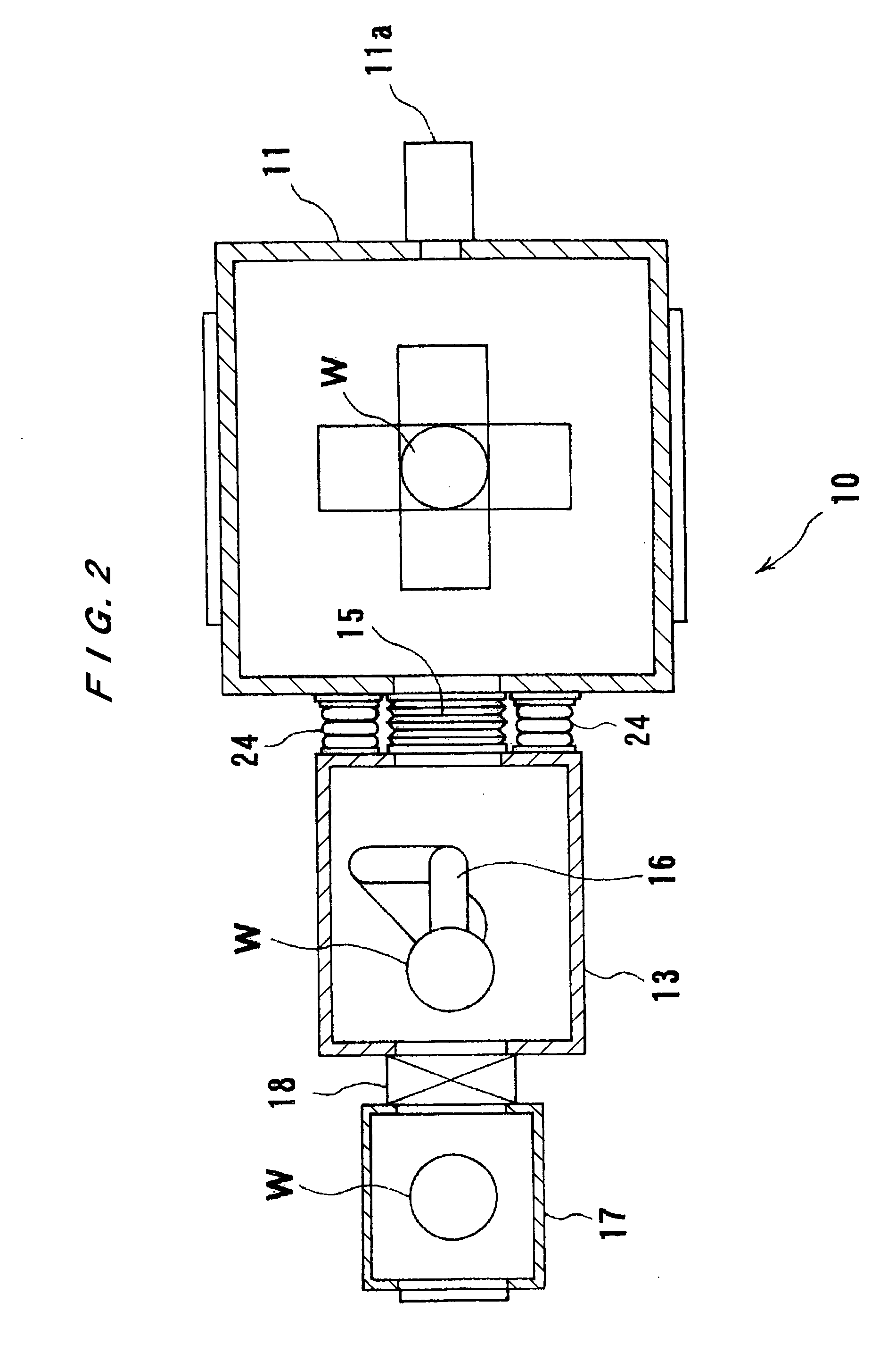
[0044] Hereinafter, embodiments of the present invention will be described with reference to the attached drawings. FIGS. 1 through 10 are views showing a device processing apparatus for performing various kinds of device processes. This device processing apparatus has a vibration isolation system according to the embodiments of the present invention. In these drawings, like or corresponding parts are denoted by the same reference numerals, and will not be described repetitively.

[0045] As shown in FIGS. 1 and 2, a semiconductor processing apparatus (device processing apparatus) 10 comprises a vacuum processing unit 12 having a vacuum chamber 11. The vacuum processing unit 12 is placed on vibration isolation units 21 each comprising an air spring. The vibration isolation units 21 isolate or damp vibration transmitted from a floor G to the vacuum processing unit 12.

[0046] The vacuum chamber 11 defines a space therein for processing a work W and has an outlet 11a formed in a side sur...


PUM

PropertyMeasurementUnit
pressureaaaaaaaaaa
rotational displacementaaaaaaaaaa
displacementaaaaaaaaaa

Abstract

The present invention provides a vibration isolation system which can prevent transmission of vibration from a transfer unit or other unit to a vacuum chamber, and can accurately perform positioning of the vacuum chamber connected to an elastic member having a simple structure and a transfer space therein. The present invention includes a vacuum chamber (11) placed on a vibration isolation unit, a transfer chamber (13) having a transfer space through which a work is transferred into the vacuum chamber (11), an elastic member (15) for connecting the vacuum chamber (11) and the transfer chamber (13), an actuator (24, 24) for elastically supporting the vacuum chamber (11) with respect to a fixed-side member, a position sensor (22) for detecting a displacement of the vacuum chamber (11) with respect to the fixed-side member, and a control unit (23) for controlling the actuator (24) based on output of the position sensor.

Description

BACKGROUND OF THE INVENTION [0001] 1. Field of the Invention [0002] The present invention relates to a vibration isolation system for a vacuum chamber, and more particularly to a vibration isolation system for use in a device processing apparatus for processing a work in a vacuum chamber connected to a fixed-side chamber. The present invention also relates to a vibration isolation system for use in a device processing apparatus for performing processes such as machining, assembling, inspection, and fabrication of a work under vacuum in a vacuum chamber connected to a fixed-side chamber. The present invention also relates to a device processing apparatus and device processing method for performing machining, assembling, inspection, and fabrication of a work with use of such a vibration isolation system. [0003] 2. Description of the Related Art [0004] Microfabrication has recently been progressing in a semiconductor processing apparatus and the like. Such apparatuses are required to p...

Claims


Application Information

Patent Timeline
Patent Type & Authority Applications(United States)
IPC IPC(8): H01L21/00F16F15/02F04B37/14F04B39/00F16F15/023F16F15/027H01L21/677
CPCF04B37/14F04B39/0044Y10T29/41H01L21/6719H01L21/67288F16F15/0275
Inventor SATOH, ICHIJUSHINODA, SETSUJIJONO, YOSHINORINISHIHASHI, TSUTOMU
Owner EBARA CORP
Learn More