
Safety circuit for media-operated consumers and process for its operation

a technology for safety circuits and consumers, applied in mechanical equipment, steam engine plants, jet propulsion plants, etc., can solve the problems of inability to effectively monitor the operating situation of the turbine, the failure of the safety circuit is relatively easy to occur, and the failure of the safety circuit to be completely destroyed, etc., to achieve short switch-back times and high availability

Inactive Publication Date: 2006-03-02
HYDAC SYST
View PDF7 Cites 15 Cited by
  • Summary
  • Abstract
  • Description
  • Claims
  • Application Information

AI Technical Summary

Benefits of technology

[0005] These objects are basically achieved by a safety circuit and an operating process where at least one further solenoid valve is connected at least to one of the other solenoid valves such that only with simultaneous triggering of at least two solenoid valves does at least one control valve, connected to the fluid circuit, act on the actuating device (lifting cylinder with plate spring assembly). Each individual essential component of the safety circuit, especially in the form of valves, can be permanently checked regardless of whether the power plant is in operation or has been shut down. Even in operation of the plant, it is possible to always check some of the valves. With other components, especially in the form of other solenoid valves, it is possible to ensure the safety function, so that high availability for the entire plant results therefrom. The solenoid valves used can be optimized to the respective safety application so that here very short switch-back times can ensue, even when using the spring resetting, as is conventional in these valve for the valve piston.
[0006] With the safety circuit of the present invention, operation is possible in which, in specifiable time cycles, the individual solenoid valves can be checked for their operating reliability, for example from a control room. Always, at least two solenoid valves can be excluded from the pertinent testing to ensure the redundant safety function for the respective consumer. The safety circuit can trigger a specifiable oil-volumetric flow in a short time (60-80 ms), almost unpressurized to the tank side of the fluid circuit, to thus relieve the actuating device of its trigger pressure. For example, under the action of an energy storage device, such as a plate spring, the actuating device, preferably in the form of a spring-loaded lifting cylinder, can induce triggering of the quick-action valve to cut off the consumer, preferably in the form of a steam or gas turbine, from its flow of medium (steam). To implement this safety concept, the respective solenoid valves of the safety circuit are preferably connected to one another to carry fluid in the form of a series connection, such that one output of one valve is always connected to carry fluid to the input of another valve. At least one input control line of the respective control valve is connected to the input side of at least one assignable solenoid valve.

Problems solved by technology

This arrangement conventionally results in the turbine having a tendency to run in the direction of overspeed which can lead to its destruction.
Malfunctions can relatively easily occur in the safety circuit, for example, when the actual switching function of the solenoid valve is disrupted by fouling or the like.
Uncertainties in the safety circuit itself lead, of course, to uncertain conditions in the effective monitoring of the operating situation of the turbine.
In the event of a process upset by failure of the safety circuit, major damage to the affected turbine can occur in the extreme case.

Method used


Image

  • Safety circuit for media-operated consumers and process for its operation
  • Safety circuit for media-operated consumers and process for its operation
  • Safety circuit for media-operated consumers and process for its operation

Examples


Embodiment Construction

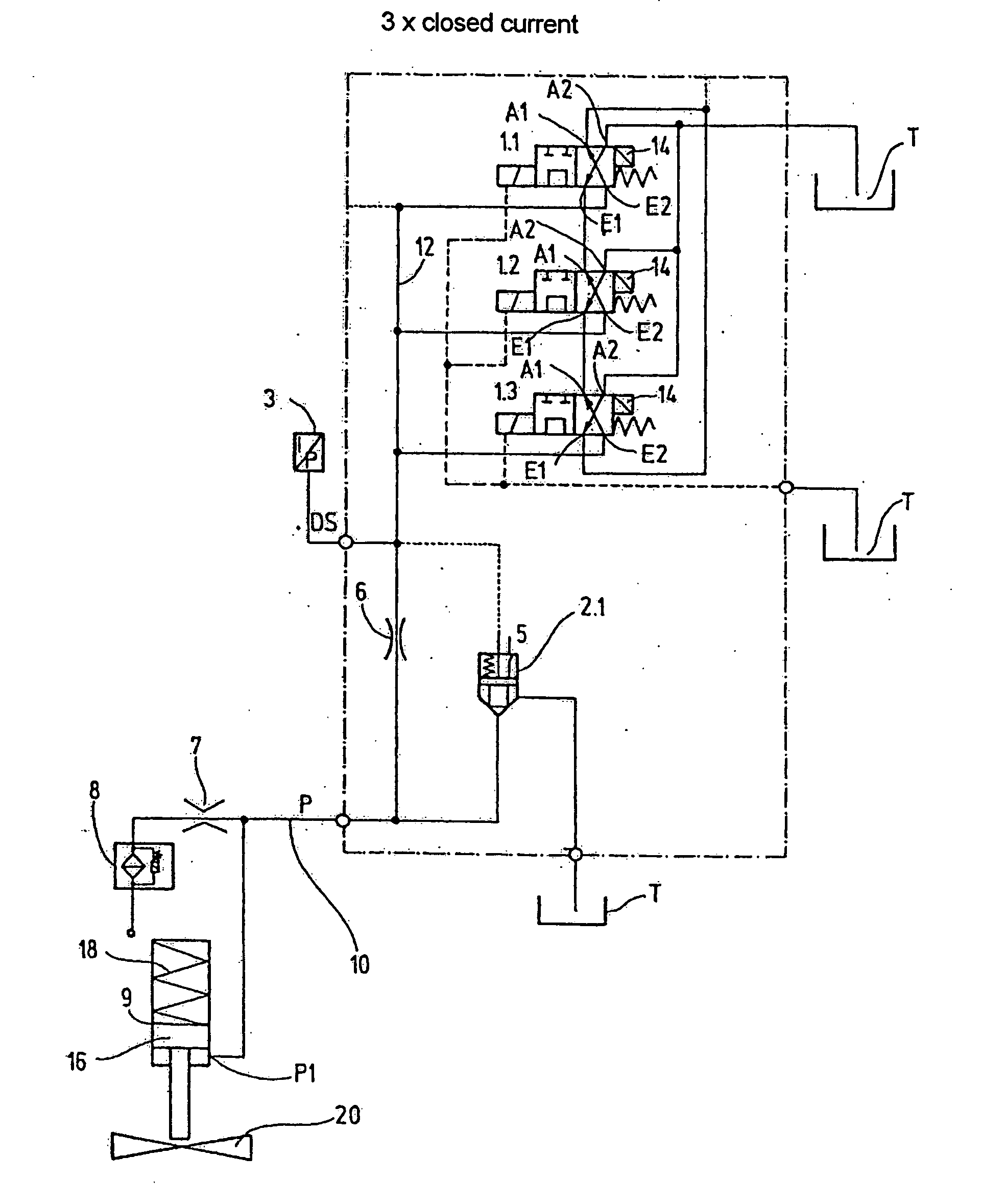
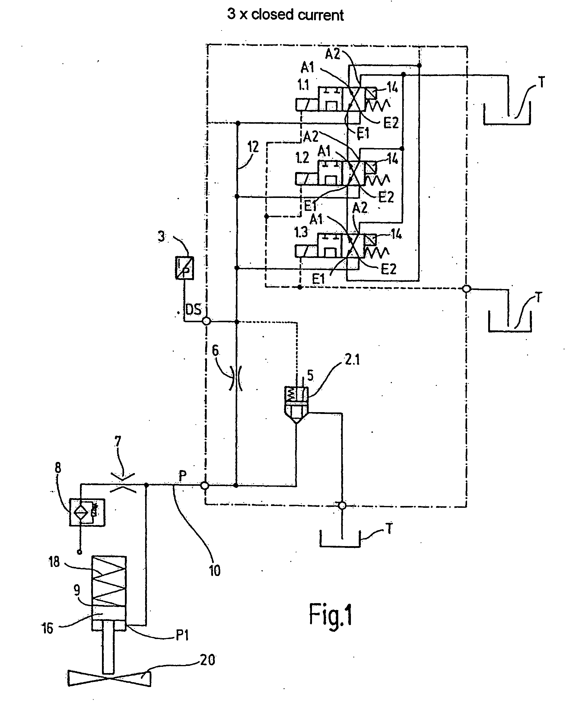
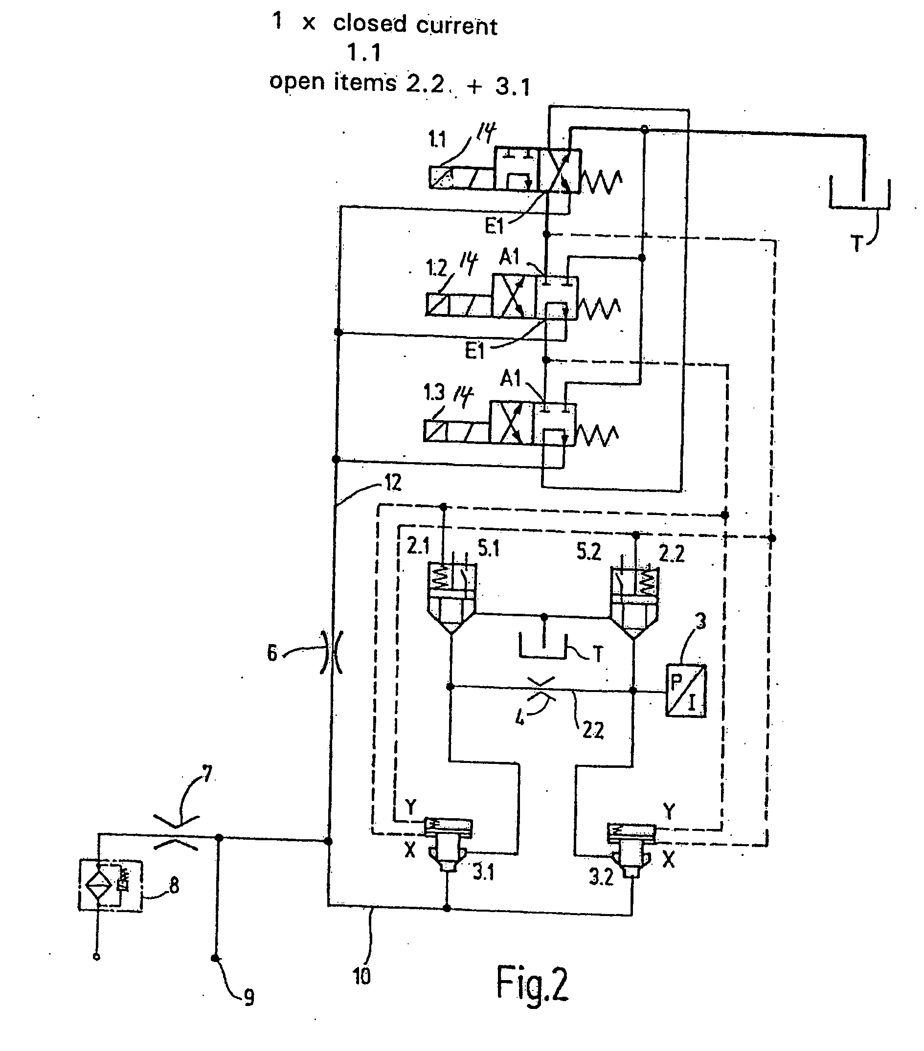
[0012] The basic structure of the safety circuit will be described first using the first embodiment of FIG. 1. The safety circuit of the present invention has three solenoid valves 1.1, 1.2, and 1.3. The safety circuit as shown in FIG. 1 has a single cartridge valve 2.1. At a tapping point, DS the system pressure can be detected by an electrical pressure transducer 3. The cartridge valve 2.1 is spring-loaded and has a proximity or limit switch 5 to detect the operating position of the cartridge valve 2.1. The safety circuit is provided with a choke 6 and a choke or orifice 7. This orifice 7 leads to a filter unit 8 which in turn is connected on the input side to part of the fluid circuit 10 and through which operating fluid under pressure is conveyed. An actuating device 9 between the connecting point P and the choke 7 discharges into the fluid circuit 10.

[0013] All three solenoid valves 1.1, 1.2, 1.3 are shown in their closed-current position, that is, in their de-energized positi...


PUM

PropertyMeasurementUnit
frequencyaaaaaaaaaa
pressureaaaaaaaaaa
pressuresaaaaaaaaaa

Abstract

A safety circuit for media-operated consumers, such as steam turbines or gas turbines, includes at least one first solenoid valve (1.1) which acts on a fluid circuit. An actuating device (9) can be connected to the fluid circuit, and acts at the same time on the operating behavior of the consumer. At least one other solenoid valve (1.2, 1.3) is connected at least to one of the other solenoid valves (1.1) such that only with simultaneous triggering of at least two solenoid valves (1.1, 1.2, 1.3) does at least one control valve (2.1), connected to the fluid circuit (10) act on the actuating device (9). Permanent verifiability can occur with simultaneous implementation of the safety function. A process for operating the safety circuit is also involved.

Description

BACKGROUND OF THE INVENTION [0001] In conventional power plants, consumers such as steam or gas turbines, are driven by live steam from the boiler. The mass flow is routed through the live steam line. The control of the mass steam flow takes place by interposed turbine control valves. The conventional rated speed of a pertinent turbine for producing a 50 Hz frequency is 3000 rpm. The pertinent speed has to be kept within a narrow percentage range. So-called quick-action valves, acting as servo valves which under certain prerequisites or criteria can undergo transition into so-called “quick-action”, are connected upstream of the actual turbine control valves. A specifiable criterion is, for example, coupling failure on the turbine shaft. This arrangement conventionally results in the turbine having a tendency to run in the direction of overspeed which can lead to its destruction. In this incipient case, in a very short available time interval, a safety circuit is triggered which bloc...

Claims


Application Information

Patent Timeline
Patent Type & Authority Applications(United States)
IPC IPC(8): B01D19/00F01K13/02F02C9/16F15B11/08F15B20/00
CPCF15B20/008F15B2211/31511F15B2211/329F15B2211/8755F15B2211/855F15B2211/87F15B2211/50536F01D17/145F01D9/06
Inventor SCHMIEDING, MARTIN
Owner HYDAC SYST
Features
  • Generate Ideas
  • Intellectual Property
  • Life Sciences
  • Materials
  • Tech Scout
  • Unparalleled Data Quality
  • Higher Quality Content
  • 60% Fewer Hallucinations
Learn More