Pressure fed coating roller, roller coating device, automated coating apparatus using this device

a technology of pressure fed coating roller and coating machine, which is applied in the direction of superimposed coating process, liquid/solution decomposition chemical coating, coating, etc., can solve the problems of large labor cost and large working hours, uneven coating of coating material on the roller, and extension of the coating booth, etc., to achieve uniform coating thickness.

Inactive Publication Date: 2006-03-02
KANSAI PAINT CO LTD
View PDF3 Cites 74 Cited by
  • Summary
  • Abstract
  • Description
  • Claims
  • Application Information

AI Technical Summary

Benefits of technology

[0085] With this feature, the automobile may be coated uniform in thickness, and efficiently.

Problems solved by technology

This method is difficult in uniformly applying the coating material onto the entire roller, resulting in an uneven coating of the coating material on the roller.
This process involves many problems: it needs great man-hours, much labor costs and large working hours, and extension of the coating booth.
There is no chance that the coating material drops from the roller type coating device 80 and resultantly, dirt sticks to the car body, and working environment is deteriorated.
To wash off the dirt, much labor is needed.
Accordingly, it is difficult to uniformly apply the coating material to the entire roller.
Accordingly, the roller type coating device is not easy to handle for the layman.
Therefore, a sufficient film thickness cannot be secured.
However, it is difficult to secure a uniform coating by the recoating.
If so, a considerable amount of coating material will stay within the roller.
The coating material having a sufficient pressure fails to reach the partitioning plate located on the deep part of the coating-material feeding pipe 101, and it is difficult to uniformly coat the object to be coated.
Thus, the problems mentioned above cannot be solved by the roller type coating device described in Patent Document 2 in which the coating material is fed to the roller from both ends of the roller and the roller is supported at both ends thereof.
None of those conventional roller type coating devices including the last mentioned device are not automated.
That is, the coating process is not automated.
When the roller type coating device is applied to the coating of an object to be coated of which the surface to be coated is curved, it is difficult to apply the roller brush uniformly over the curved surface.
Accordingly, it is considered that it is more difficult to automatize such a coating work.
Therefore, the uniform coating is impossible.
The coating film formed by the dust part is manually peeled off, and the peeling-off work needs considerably troublesome labor.
Thus, the automatic coating apparatus of the spray type has practically been used, but is still unsatisfactory in its performances.
The conventional and known roller coating device (one- and both-end coating pressure feed rollers) is not suitable for the automatic coating process and hence, it is not automated.
That is, the coating process is not automated.
When the roller coating device is applied to the coating of an object to be coated, of which the coating surface is a curved surface, it is difficult to apply the roller brush uniformly over the curved surface.
Accordingly, it is considered that it is more difficult to automatize such a coating process.
It was found that in the coating by the automated coating apparatus, one problem to be solved is present.

Method used


Image

  • Pressure fed coating roller, roller coating device, automated coating apparatus using this device
  • Pressure fed coating roller, roller coating device, automated coating apparatus using this device
  • Pressure fed coating roller, roller coating device, automated coating apparatus using this device

Examples


second embodiment

of the Invention

[0303] A second embodiment of the invention will be described.

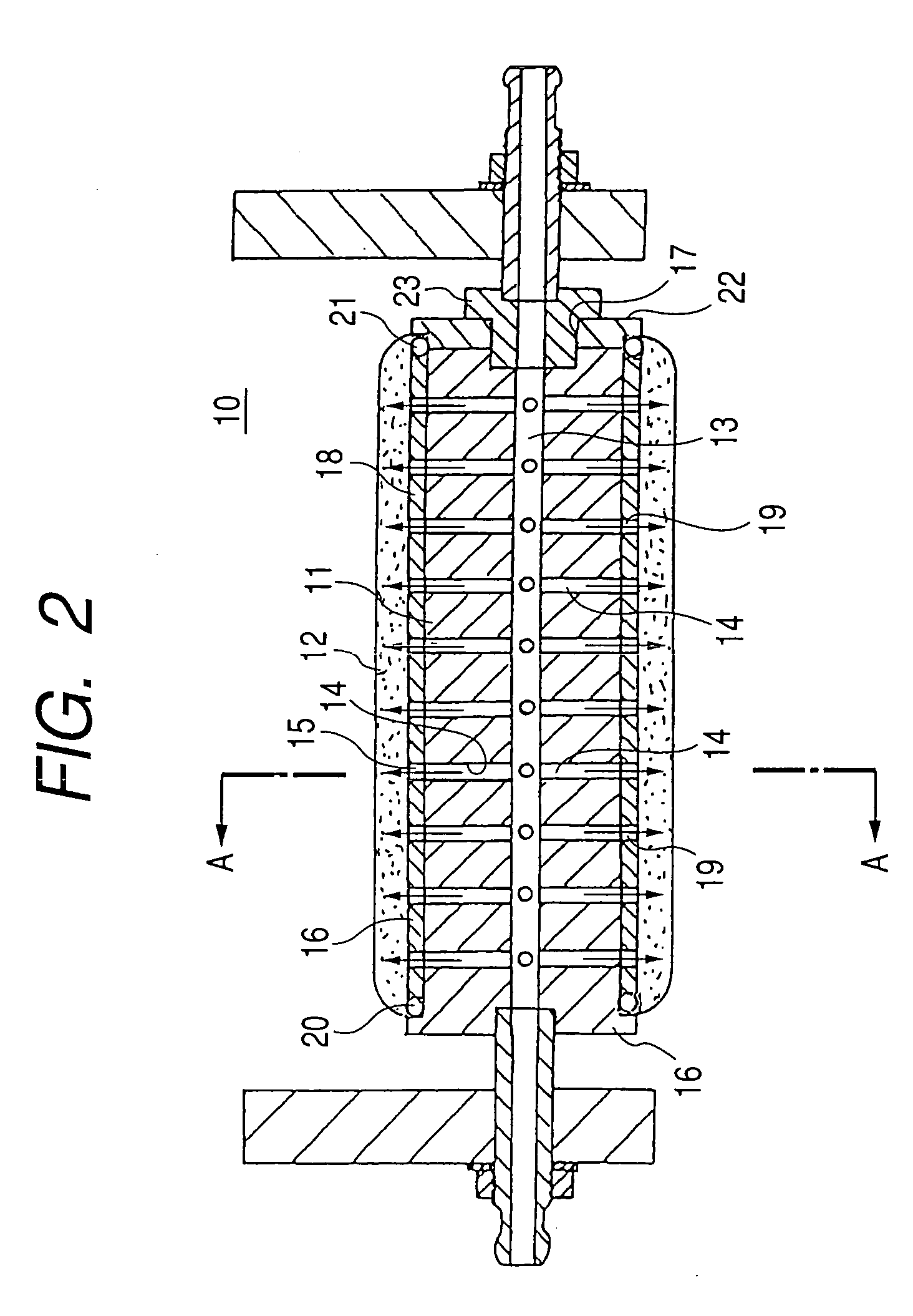
[0304] The second embodiment relates to a way of feeding a coating material to the axial center hole 13 of the solid cylindrical body 11 including the coating pressure feed roller, and a way of supporting the solid cylindrical body 11.

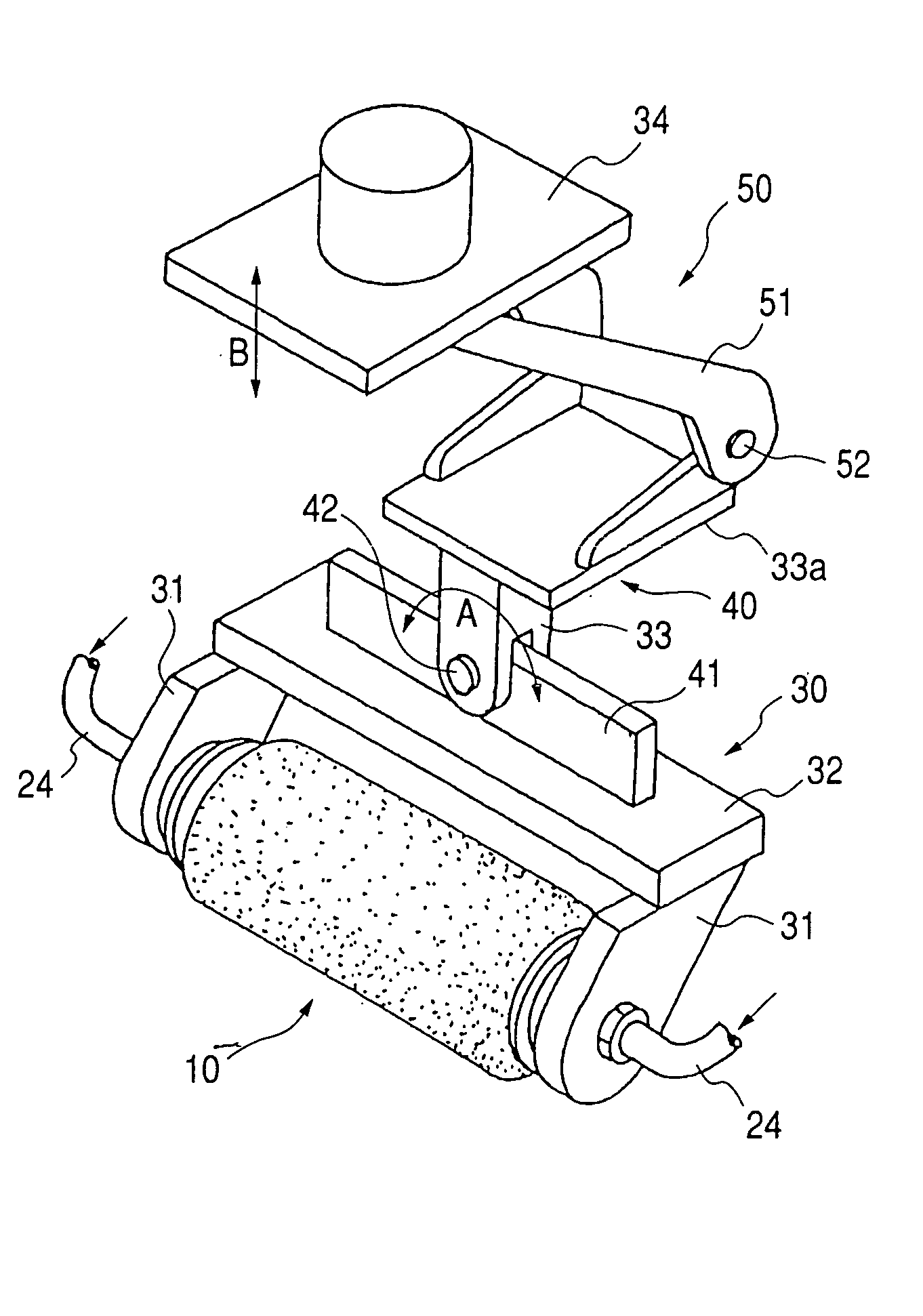
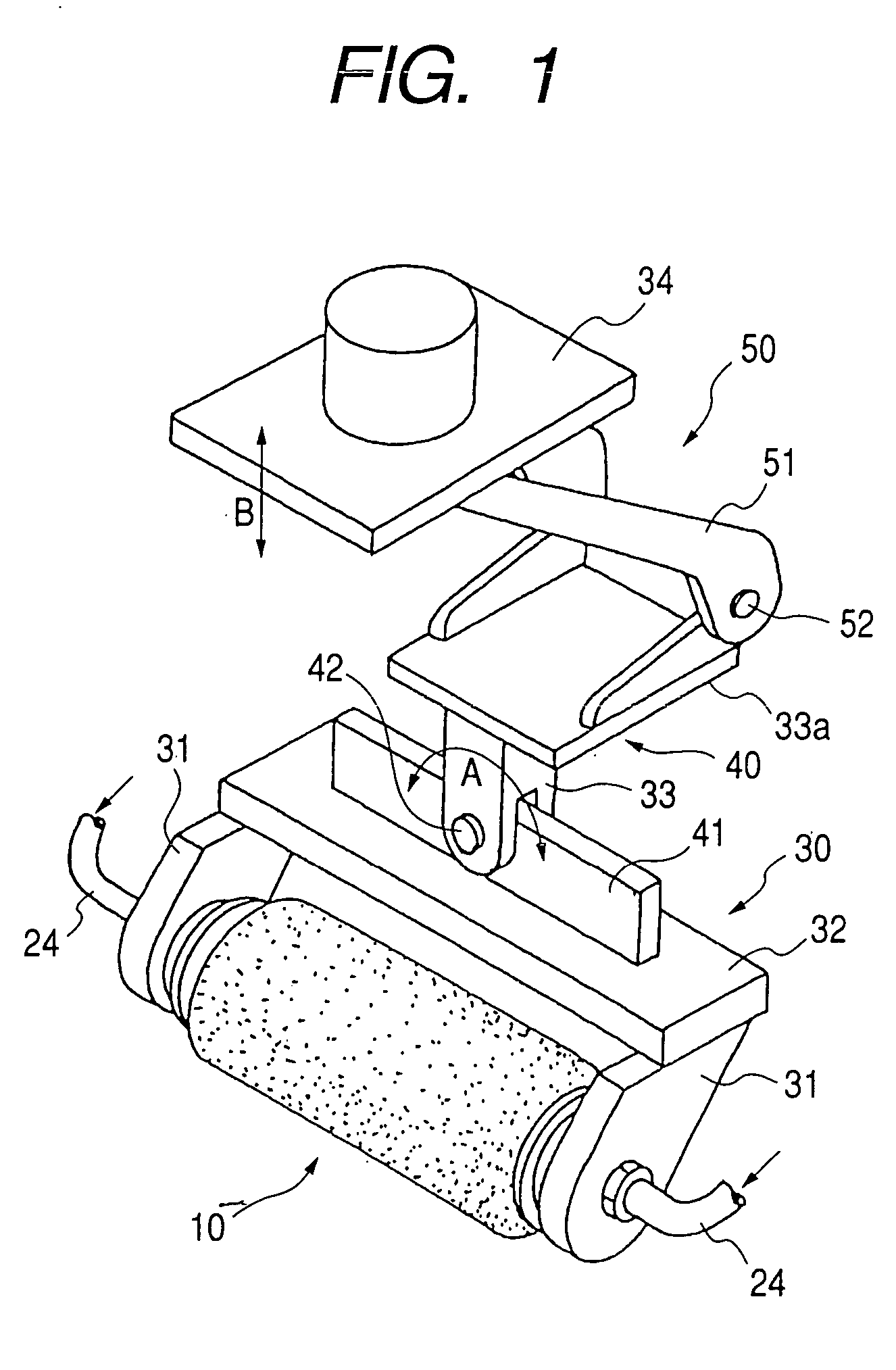
[0305] As described in connection with FIG. 29, in the conventional roller coating device, the coating material is fed to the roller from one end of the roller, and the roller is supported in a cantilever fashion. Accordingly, the conventional roller coating device suffers from the disadvantages as mentioned above. In the instant embodiment, coating-material press feeding pipes 24 (see FIG. 1) are connected to both ends of the axial center hole 13 of the solid cylindrical body 11. The coating pressure feed roller is rotatably supported at both ends by arms 31, and the arms 31 are couple together by a lower frame 32, whereby a support 30 is formed.

[0306] The coating-materia...

third embodiment

of the Invention

[0309] A third embodiment of the invention will be described.

[0310] A coating device of the third embodiment, as shown in FIG. 1, includes a turnable support mechanism 40 for turning the support 30 which supports the roller brush assembly 10 in a direction of an arrow A, and a vertically movable support mechanism 50 for vertically moving the same in a direction of an arrow B.

[0311] The support 30 includes the two arms 31 and the lower frame 32 bridged between those arms. The two arms 31 rotatably support the roller brush assembly 10 therebetween. The support 30 is mounted to the turnable support mechanism 40, and the turnable support mechanism 40 is mounted to the vertically movable support mechanism 50.

[0312] The turnable support mechanism 40 is constructed such that a plate 41 extends on the upper surface of the lower frame 32 in parallel with the axis of the roller brush assembly 10. The plate is rotatably coupled to the intermediate frame 33 by means of a pin ...

fourth embodiment

of the Invention

[0342] A fourth embodiment of the invention will be described with reference to FIGS. 11 and 12. The fourth embodiment relates to an automatic coating, and in the automatic coating, the curved-surface operable roller coating device according to the third embodiment is attached to the tip of a robot arm.

[0343]FIG. 11 is a diagram showing an automatic coating apparatus which is a fourth embodiment of the invention. FIG. 12 is a block diagram showing a central control unit in FIG. 11.

[0344] In FIG. 11, reference numeral 70 is an automatic coating apparatus; 71 is a coating robot; 72 is a curved-surface operable roller coating device attached to the tip of a movable part of the coating robot 71; 73 is a coating-material pressure feed pump; 731 is a pump control unit; and 74 is a robot body, which is a multiarticulate robot of the teaching playback type. The robot body 74 includes a movable part 741 operably coupled, and its robot operation is controlled by a robot cont...


PUM

PropertyMeasurementUnit
opening angleaaaaaaaaaa
angleaaaaaaaaaa
surface temperatureaaaaaaaaaa

Abstract

An object of the present invention is to provide a coating device of the roller type which reduces a waste of coating material and distributes the coating material uniformly to the roller brush.
The coating device includes a sold cylindrical body (11) being solid except an axial center hole (13), and radial holes (14) radially extended from a plurality of positions of the axial center hole (11), a roller brush (12) applied to the outer periphery of the solid cylindrical body (11), coating-material press feeding pipes (24) connected to both ends of the axial center hole (13) of the solid cylindrical body (11), and an arm part (31) for supporting the solid cylindrical body (11) at both ends of the solid cylindrical body (11). Those components are entirely supported by a turnable support mechanism (40) and a vertically movable support mechanism (50).

Description

TECHNICAL FIELD [0001] The present invention relates to a coating pressure feed roller, a roller coating device, a curved-surface operable roller coating device, and a automated coating apparatus using those devices and a coating method. More particularly, the invention relates to a roller coating well adaptable for the feeding of a coating material or the like to a roller brush by using a pump or the like. BACKGROUND ART [0002] The roller coating device has been used in various fields. The roller coating device is used in an automobile manufacturing factory, for example. In the factory, the roller coating device is used for forming a protecting film on a surface of a coating film of the car in order to protect the coating film against rain water, iron powder, pollen, bird droppings and the like and hence to prevent coating quality deterioration. [0003] In the known roller coating device, the roller is manually rotated in a coating material reservoir containing a coating material, a...

Claims


Application Information

Patent Timeline
Patent Type & Authority Applications(United States)
IPC IPC(8): B05D5/00B05C1/08B05C11/00B05C1/06B05C1/10B05C17/02B05C17/03B05D1/26B05D1/28
CPCB05C1/10B05C17/0217B05D1/28B05C17/0308B05D1/26B05C17/0232B05C17/02
Inventor TSUSHI, TOSHIHIROABE, SHIGEYUKIHIRAI, HARUO
Owner KANSAI PAINT CO LTD
Why Eureka
Try Eureka