In situ remedial alternative and aquifer properties evaluation probe system

a technology of aquifer properties and probes, which is applied in the field of in situ remedial alternatives and aquifer properties evaluation probe systems, can solve the problems that prior art does not accommodate the ejection of sealants from probes, and achieve the effect of faster and more easily automated

Inactive Publication Date: 2006-03-02
OXYTEC LLC
View PDF6 Cites 79 Cited by
  • Summary
  • Abstract
  • Description
  • Claims
  • Application Information

AI Technical Summary

Benefits of technology

[0018] The present invention performs relative permeability profiling in lieu of hydraulic conductivity profiling, because it is faster and more easily automated than hydraulic conductivity testing while yielding information about likely stratigraphy and contaminant migration pathways. During relative permeability testing with DPT, th

Problems solved by technology

The prior art does not accommodate ejection of a seal

Method used


Image

  • In situ remedial alternative and aquifer properties evaluation probe system
  • In situ remedial alternative and aquifer properties evaluation probe system
  • In situ remedial alternative and aquifer properties evaluation probe system

Examples


Embodiment Construction

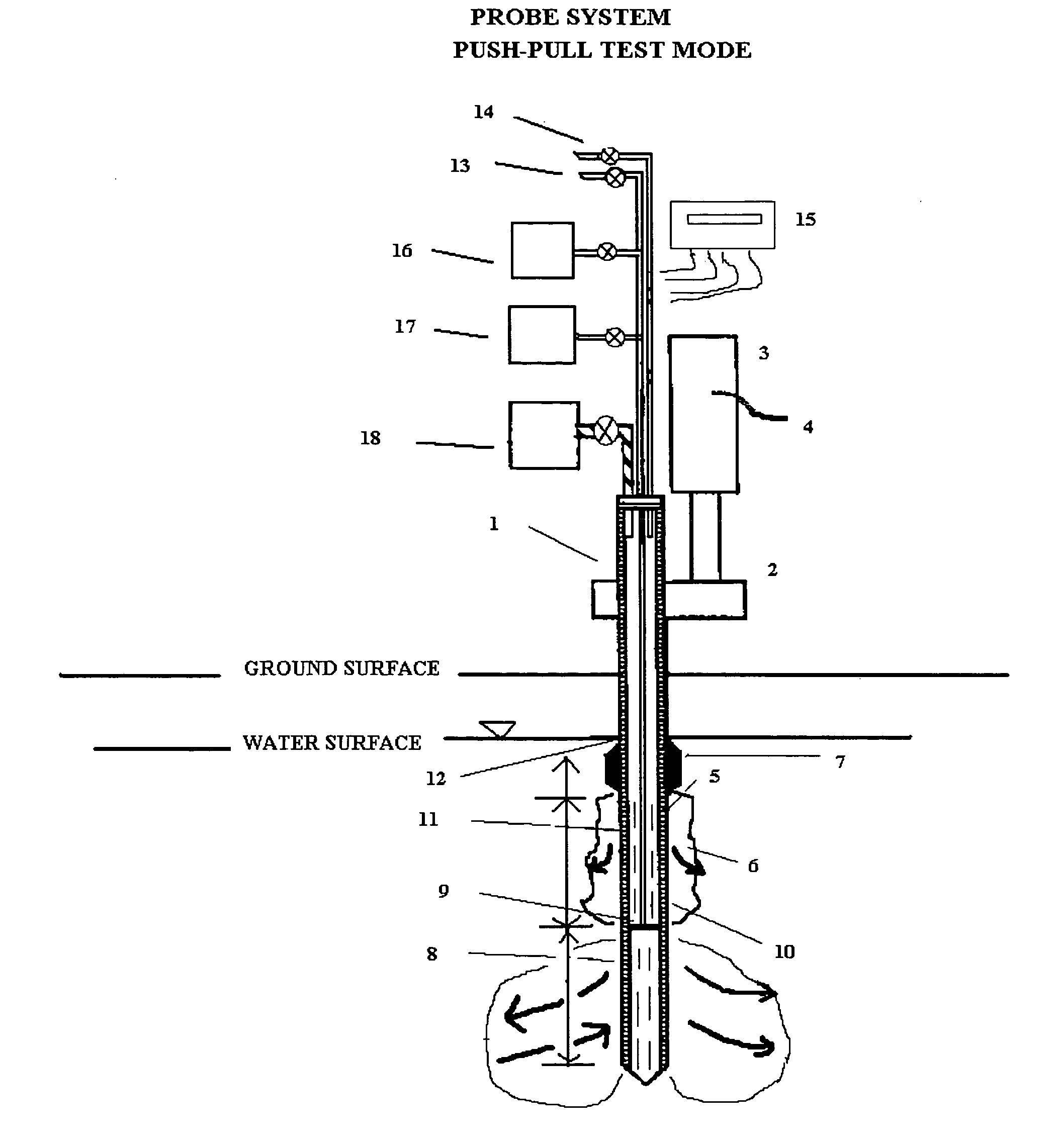
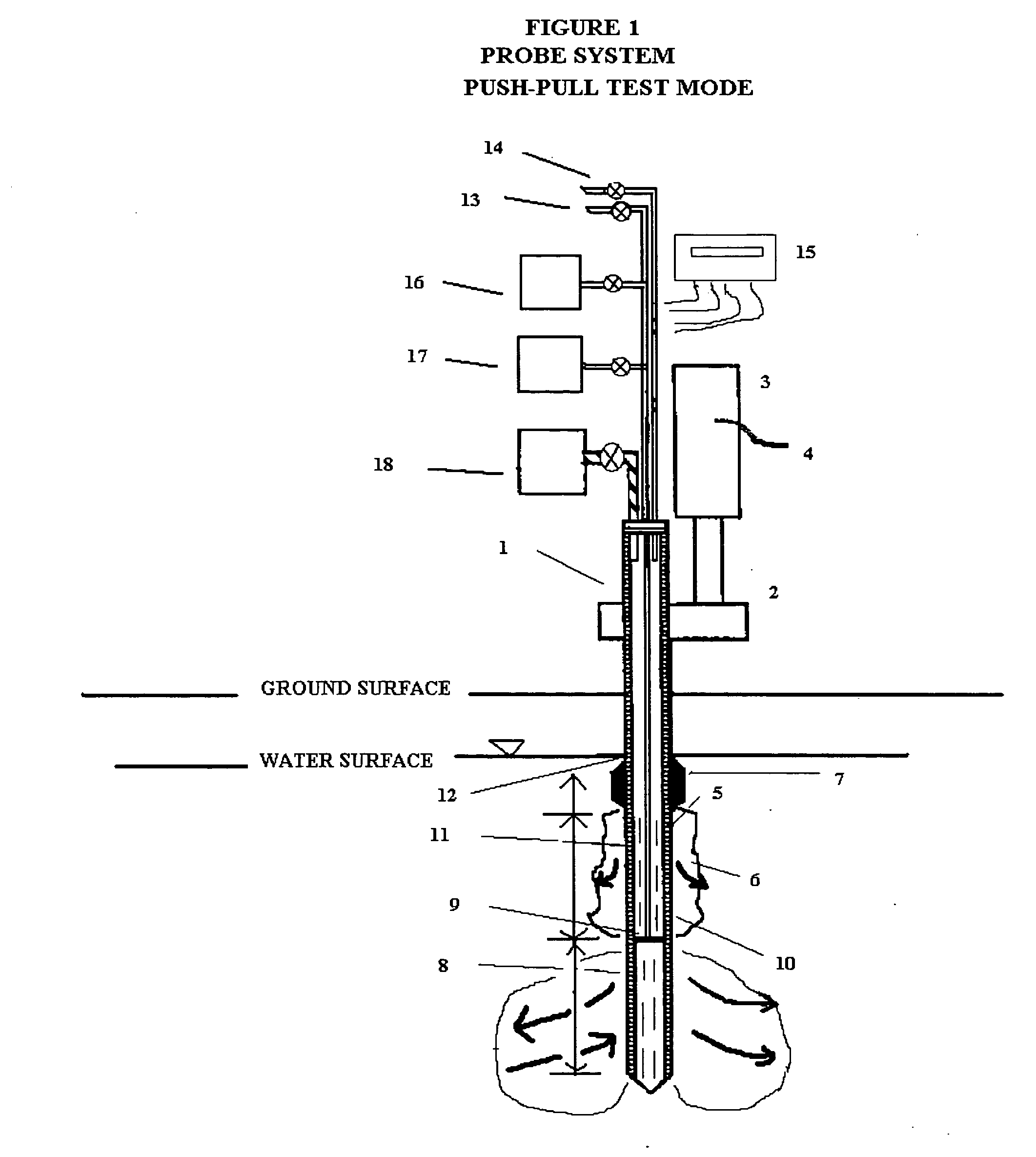
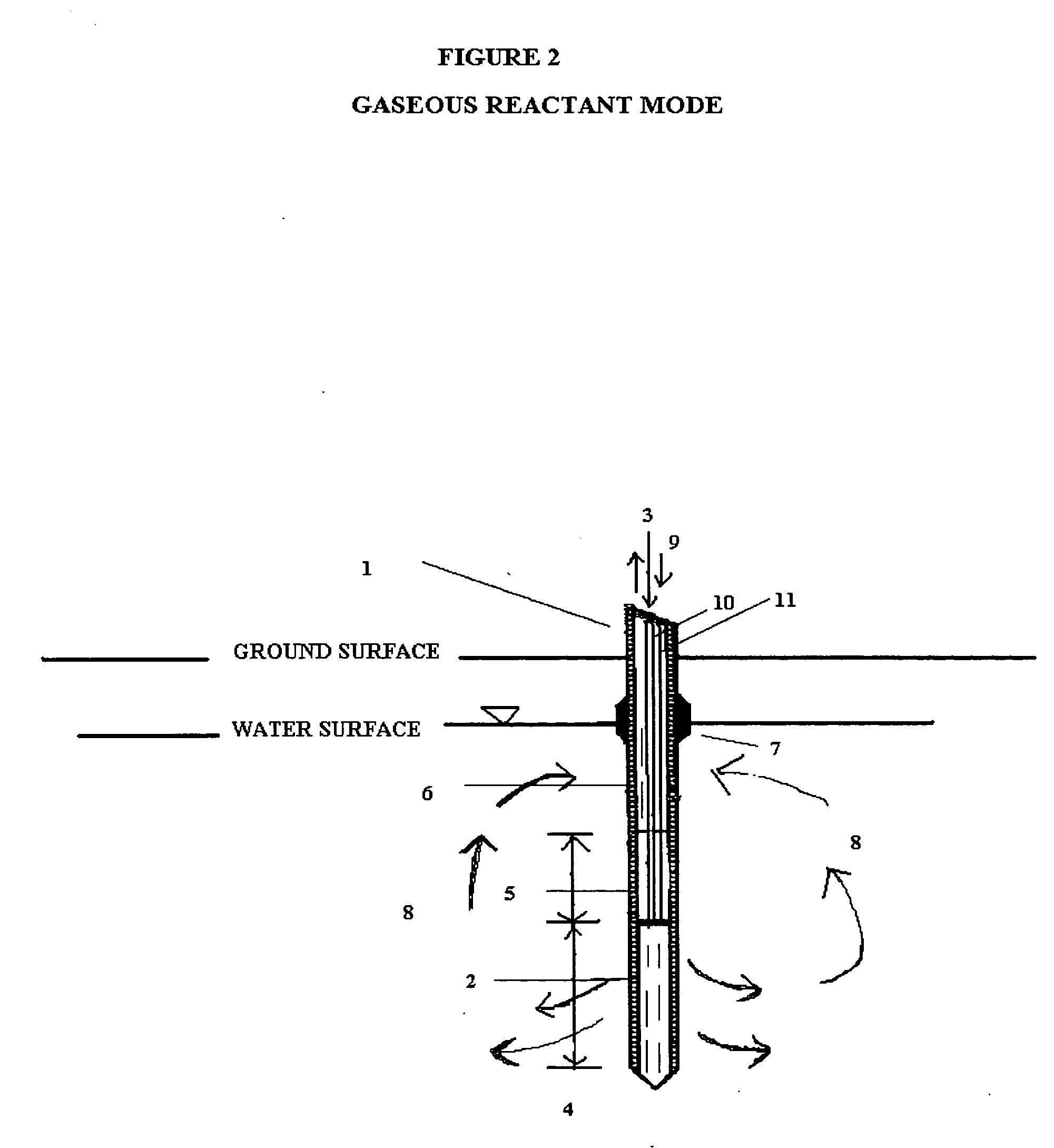
[0034] The probe system described here is multi-purpose in that it was designed: 1) to measure the relative permeability of the subsurface soil and groundwater to a liquid or gas ejectant, 2) to recover soil gas, soil, or groundwater samples for contaminant analyses, 3) to measure the chemical dosage and reaction, dissolution, adsorption, desorption, leaching, or fixation rate of a reactant such as a chemical or biochemical oxidant, metallic or bimetallic dehalogenating agent, surfactant or emulsifier solution, adsorbent media regenerant, leaching or fixation reagent that is injected into the matrix and withdrawn during a push-pull test, 4) to perform combinations of the above, 5) to measure the in situ adsorption capacity of adsorbent media and subsequently measure the effectiveness of regenerant(s) for the adsorbent media, and (6) to measure the effectiveness of a treated soil column for inorganic contaminant(s) leaching or fixation. In addition to being an in situ remedial altern...


PUM

PropertyMeasurementUnit
Temperatureaaaaaaaaaa
Pressureaaaaaaaaaa
Widthaaaaaaaaaa

Abstract

In general, the purpose of the probe system is to provide improved rapid field methods using re-designed direct push technology (DPT) and “push-pull testing” concepts to evaluate in situ chemical, biochemical, surfactant, adsorptive media, and leaching and fixation remediation technologies for hazardous subsurface contaminant(s). The probe system and methods described here when applied to a hazardous waste site being considered for in situ remediation of contaminants (organic or inorganic) by the listed treatment technologies will yield information that greatly reduces the uncertainty with regards to treatment effectiveness for the in situ soil, groundwater, and contaminant(s) conditions affecting dosage requirements and reaction rate(s) for various reactants. The probe system described here is multi-purpose in that it was designed: 1) to measure the relative permeability of the subsurface soil and groundwater to a liquid or gas ejectant, 2) to recover soil gas, soil, or groundwater samples for contaminant analyses, 3) to measure the chemical dosage and reaction, dissolution, adsorption, desorption, leaching, or fixation rate of a reactant such as a chemical or biochemical oxidant, metallic or bimetallic dehalogenating agent, surfactant or emulsifier solution, adsorbent media regenerant, leaching or fixation reagent that is injected into the matrix and withdrawn during a push-pull test, 4) to perform combinations of the above, 5) to measure the in situ adsorption capacity of adsorbent media and subsequently measure the effectiveness of regenerant(s) for the adsorbent media, and (6) to measure the effectiveness of a treated soil column for inorganic contaminant(s) leaching or fixation. In addition to being an in situ remedial alternatives evaluation tool, the probe system can be used as a reactant(s) delivery device after the specific remedial technology has been selected.

Description

BACKGROUND OF THE INVENTION [0001] Both State and Federal government have strict regulations governing hazardous organic and inorganic contaminants in the environment. Subsurface soil and groundwater contamination with organic and inorganic contaminants has been the concern of State and Federal government since the 1970's. Action levels and clean-up standards have been promulgated by both State and Federal government for numerous organic and inorganic contaminants. Regulated organic contaminants in the subsurface environment include, but are not limited to: polychlorinated biphenyls (PCBs); chlorinated volatile organic compounds (CVOCs) such as tetrachloroethene (PCE), trichloroethene (TCE), trichloroethane (TCA), dichloroethene (DCE), vinyl chloride; fuel constituents such as benzene, ethylbenzene, toluene, xylene, methyl tert butyl ether (MTBE), tertiary butyl alcohol (TBA), polynuclear aromatic hydrocarbons (PAHs), ethylene dibromide (EDB); pesticides such as (but not limited to)...

Claims


Application Information

Patent Timeline
IPC IPC(8): G01N33/24
CPCG01N33/24G01N15/0826
Inventor BALL, RAYMOND G.
Owner OXYTEC LLC
Why Eureka
Try Eureka