Electrochemical synthesis of ammonia

a technology of ammonia and electrochemical synthesis, which is applied in the direction of electrolysis process, electrolysis components, etc., can solve the problems of increasing the thermal decomposition rate of ammonia, slow electrochemical reaction rate, and large-scale chemical plants and costly operating conditions, so as to prevent leakage

Inactive Publication Date: 2006-03-09
LYNTECH INC
View PDF8 Cites 73 Cited by
  • Summary
  • Abstract
  • Description
  • Claims
  • Application Information

AI Technical Summary

Benefits of technology

[0040] The apparatus will typically further comprise mixed gas (comprising hydrogen and nitrogen) inlet and outlet manifolds for providing the fluid communication between the source of gaseous reactants (hydrogen gas and nitrogen gas) and each of the porous cathode substrates, and an ammonia product gas outlet manifold for providing fluid communication between an ammonia exit port attached to the apparatus and each of the porous anode substrates. The gaseous reactants and gaseous product manifolds are selected from either an internal manifold arrangement or an external manifold arrangement. In a preferred embodiment, anodic cell frames and cathodic cell frames are disposed around the anode flow fields and porous anode substrates (and any gas diffusion layers or electrode backing layers if included) and cathode flow fields and porous cathode substrates (and any gas diffusion layers or electrode backing layers if included), respectively. These cell frames must be able to withstand the high temperatures, high pressures and harsh chemical environment of the molten salts. Accordingly, the cell frames may be made, for example, from polyimide polymers, Macor® (a machineable glass ceramic), mica, graphite, nickel, stainless steel, Inconel or Monel. It will be apparent to one skilled in the art of electolyzers that seals comprising gaskets and / or o-rings will be suitably used between certain components within an electrolytic cell and between electrolytic cells to prevent leaks. Gaskets, and o-rings may be made, for example, from Viton®, Kalrez®, silicone polymers, polyimide polymers, Macor®, mica, or graphite.
[0041] In one embodiment, the porous anode substrate and the porous cathode substrate are each selected from metal foams, metal grids, sintered metal particles, sintered metal fibers, woven and nonwoven metal cloths, perforated or etched metal sheets, porous graphite, graphite or carbon-based foams, cloths, or aerogels, and combinations thereof. Preferably, two or more of the metal components of an electrolytic cell are metallurgically bonded together, such as by a process selected from welding, brazing, soldering, sintering, fusion bonding, vacuum bonding, and combinations thereof. For example, the anodic fluid flow field may be metallurgically bonded to the bipolar plate, the cathodic fluid flow field may be metallurgically bonded to the bipolar plate, the anodic fluid flow field may be metallurgically bonded to the porous anode substrate, the cathodic fluid flow field may be metallurgically bonded to the porous cathode substrate, and combinations thereof.

Problems solved by technology

Low conversion efficiencies give rise to cost intensive, large scale chemical plants and to costly operating conditions (compression of reactant gases) in order to produce commercially viable hundreds-to-thousands of tons-per-day of ammonia in an ammonia synthesis plant.
However, the process is limited by slow electrochemical reaction rates due to low proton (H+) fluxes through the solid electrolyte at 570° C. Increasing the temperature to obtain higher proton (H+) fluxes would also increase the rate of thermal decomposition of ammonia.
A major drawback of both low (and high) temperature cathodic electrochemical processes is that the competing hydrogen gas evolution reaction takes place more readily than the formation of ammonia since recombination of adsorbed hydrogen atoms with each other is more likely to occur than reaction between adsorbed hydrogen atoms and adsorbed nitrogen molecules due to the high bond strength (˜1000 kJ mol−1 at 25° C.) of the N≡N triple bond of a nitrogen molecule.

Method used


Image

  • Electrochemical synthesis of ammonia
  • Electrochemical synthesis of ammonia
  • Electrochemical synthesis of ammonia

Examples


second embodiment

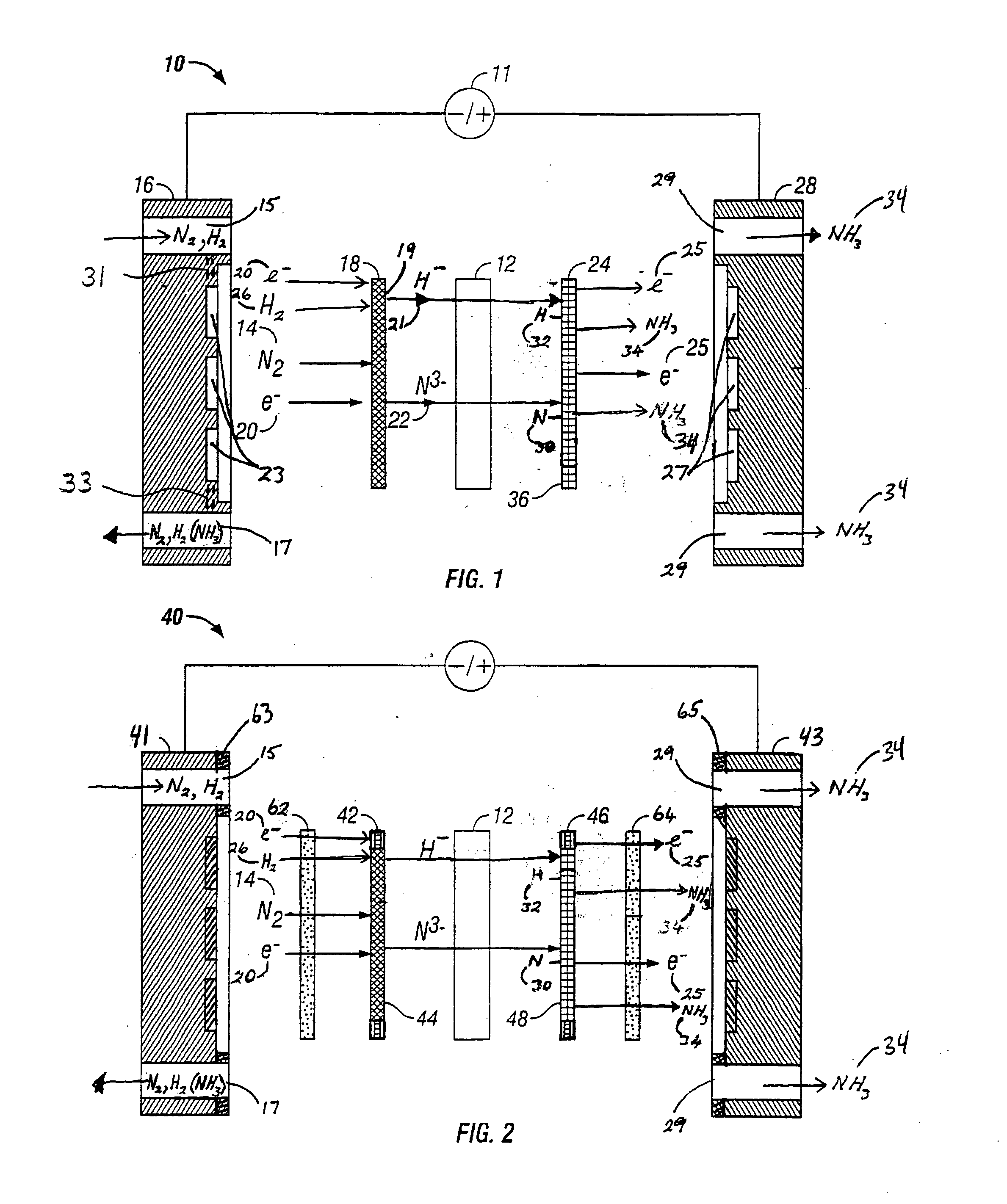
[0067]FIG. 2 is an expanded schematic flow diagram of an ammonia electrosynthesis cell 40 in accordance with the present invention. The cell 40 operates in almost identical fashion to cell 10 of FIG. 1, except that it includes a catalyzed gas diffusion electrode or a catalyzed backing electrode 42 in combination with a porous electrically conducting cathode flow field 62 and a catalyzed gas diffusion electrode or a catalyzed backing electrode 46 in combination with a porous electrically conducting anode flow field 64. A cathode flow field frame 63 encompasses the perimeter of the cathode flow field 62 and makes a leak free seal with the endplate 41. A similar frame (not shown) surrounds the cathode electrode 42 / electrolyte-matrix combination 12 / anode electrode 46 assembly. The cathode gas manifolds 15 and 17 in cathode endplate 41 are in fluid communication with the cathode flow field 62. Similarly, an anode flow field frame 65 encompasses the perimeter of the anode flow field 64 an...

third embodiment

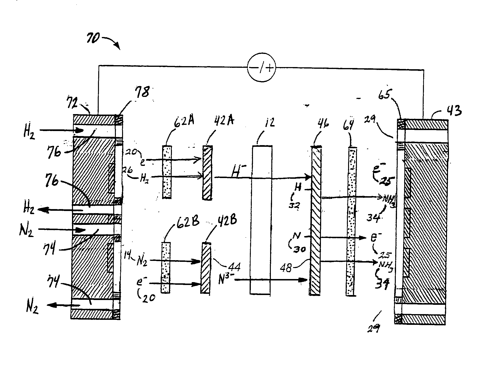
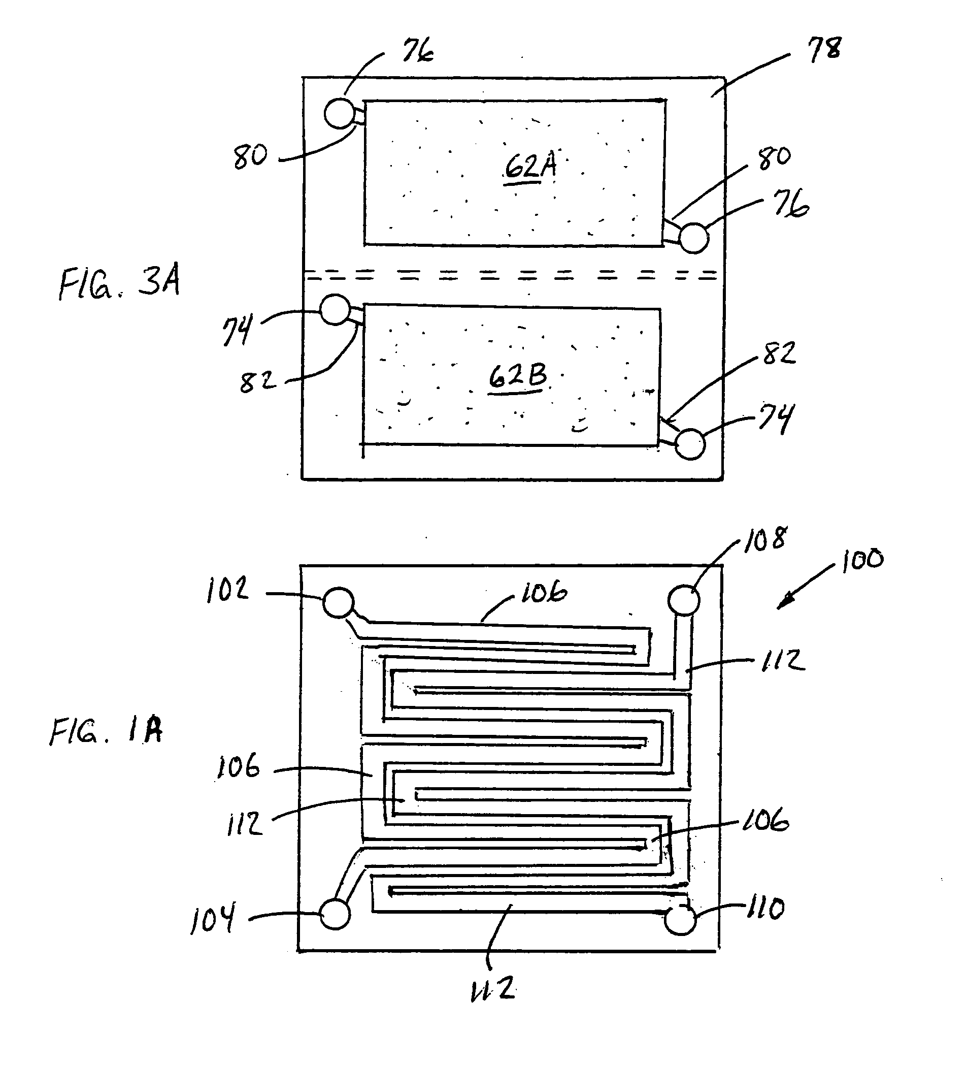
[0068]FIG. 3 is an expanded schematic flow diagram of an ammonia electrosynthesis cell 70 in accordance with the invention. The cell 70 has an cathodic endplate 72 with nitrogen gas inlet / outlet manifolds 74 that are separate from the hydrogen gas inlet / outlet manifolds 76. Furthermore, the hydrogen and nitrogen manifolds 76,74 communicate the gases to separate flow fields 62A, 62B, respectively, and, in turn, to separate electrode substrates 42A,42B, respectively. As discussed previously with respect to FIG. 1A, it may be beneficial to maintain some separation of the reactant gases to avoid ammonia generation at the cathode. Thise endplate 72 illustrates an alternative configuration to maintain that separation, but also facilitates the use of the separate flow fields and electrode substrates. In this manner, the overall cathode surface area is effectively split to provide a hydrogen cathode and a nitrogen cathode. Having the separate hydrogen cathode substrate 42A and nitrogen cath...

fourth embodiment

[0071]FIG. 4 is an expanded schematic flow diagram of another ammonia electrosynthesis cell 90 in accordance with the invention, the cell 90 having two half cathodes enplates 92,94 coupled to separate power supplies 96,98, respectively. Two half cathodes are formed by the combinations of the endplates 92,94, the flowfields 62A,62B, and the electrode substrates 42A,42B, respectively. While cell 90 have many similarities with cell 70, the endplates 92,94 are electrically isolated by an insulative flowfield frame 78 can be made in the same manner as in FIG. 3, preferably with the insulator element 99 being an insulative material to provide support for the adjacent central portion of the frame 78. An electronically insulative frame would also be placed around the cathode substrates 42A,42B (not shown) to maintain electrical isolation of the two cathode substrates. Accordingly, the electronic potential or voltage of the two half cathodes can be separately controlled to further optimize t...


PUM

PropertyMeasurementUnit
temperatureaaaaaaaaaa
pressureaaaaaaaaaa

Abstract

A method for the anodic electrochemical synthesis of ammonia gas. The method comprises providing an electrolyte between an anode and a cathode, providing nitrogen and hydrogen gases to the cathode, oxidizing negatively charged nitrogen-containing species and negatively charged hydrogen-containing species present in the electrolyte at the anode to form adsorbed nitrogen species and adsorbed hydrogen species, respectively, and reacting the adsorbed nitrogen species with the adsorbed hydrogen species to form ammonia. Nitrogen and hydrogen gases may be provided through a porous cathode substrate. The negatively charged nitrogen-containing species in the electrolyte may be produced by reducing nitrogen gas at the cathode and/or by supplying a nitrogen-containing salt, such as lithium nitride, into the molten salt electrolyte. Similarly, the negatively charged hydrogen-containing species in the electrolyte may be produced by reducing hydrogen gas at the cathode and/or by supplying a hydrogen-containing salt, such as lithium hydride, into the molten salt electrolyte.

Description

[0001] This application claims priority from U.S. provisional patent application 60 / 607,653, filed on Sep. 7, 2004.BACKGROUND OF THE INVENTION [0002] 1. Field of the Invention [0003] This invention relates to an electrochemical method and apparatus for the synthesis of ammonia. In particular, the invention relates to an anodic electrochemical method and apparatus for the electrosynthesis of ammonia. [0004] 2. Background to the Related Art [0005] Ammonia (NH3) is a colorless alkaline gas that is lighter than air and possesses a unique, penetrating odor. Since nitrogen is an essential element to plant growth, the value of nitrogen compounds as an ingredient of mineral fertilizers, was recognized as early as 1840. Until the early 1900's, the nitrogen source in farm soils was entirely derived from natural sources. Haber and Bosch pioneered the synthesis of ammonia directly from hydrogen gas and nitrogen gas on a commercial scale in 1913. Further developments in large-scale ammonia produ...

Claims


Application Information

Patent Timeline
Patent Type & Authority Applications(United States)
IPC IPC(8): C25B1/00
CPCC25B1/00C25B1/27
Inventor MURPHY, OLIVER J.DENVIR, ADRIAN J.TEODORESCU, SORIN G.USELTON, KYLE B.
Owner LYNTECH INC
Why Eureka
Try Eureka