Thermal type mass flow rate sensor made of corrosion resistant metal, and fluid supply equipment using the same

a mass flow rate sensor and corrosion resistance technology, which is applied in the direction of volume/mass flow measurement, measurement devices, instruments, etc., can solve the problems of many problems to be solved, uneven property of products, slow response speed of mass flow rate sensors, etc., and achieve excellent corrosion resistance, less corrosion resistance, and fast response speed

Active Publication Date: 2006-03-16
FUJIKIN INC
View PDF12 Cites 11 Cited by
  • Summary
  • Abstract
  • Description
  • Claims
  • Application Information

AI Technical Summary

Benefits of technology

[0016] The present invention is to solve the afore-mentioned problems with the conventional mass flow rate sensor such as ① that unevenness in property among products might be caused and the response speed is low with a capillary thermal type mass flow rate sensor, and ② that the emission of particles, the occurrence of outside leaks and the like cannot be avoided with a silicon-made ultra-small-sized thermal type mass flow rate sensor in addition that it is less corrosion resistant. It is a primary object of the present invention to provide a corrosion resistant metal made thermal type mass flow rate sensor and a fluid supply device for which the sensor is employed, thus allowing to manufacture ultra-small-sized and consistent products by making use of micro-machine technologies, to achieve the excellent corrosion resistance and the fast response speed, and also to enable to make it particle-free and outside leak-less.
[0017] Inventors of the present invention have come to an idea, by employing micro-machine technologies, to prevent unevenness in quality among mass flow rate sensors manufactured, to enhance corrosion resistance and responsiveness, and further to achieve to make it particle-free and outside leak-less by forming two pieces of temperature detecting resistance, a heater, a lead wire to connect elements and the like required for a mass flow rate sensor by using a thin film body on the substrate made of the corrosion resistant metal such as stainless steel and the like; and manufactured trial mass flow rate sensors, and the tests were repeated on them based on the said idea.

Problems solved by technology

However, the capillary thermal type mass flow rate sensor is required to be equipped with a resistance wire for a heater to be wound to heat a capillary tube, thus causing a problem that may lead to unevenness in property among the products.
Another problem may be that the response speed of a mass flow rate sensor becomes slow due to the relatively large heat capacities of the capillary tube and the resistance wire for a heater.
However, it is noted that there exist many problems to be solved with the said silicon-made ultra-small-sized thermal type mass flow rate sensor.
Therefore, a fundamental difficulty is that it can be easily corroded by fluids in a halogen family and the like.
Furthermore, organic materials such as an epoxy resin, an O-ring and the like are used as sealing materials for the mass flow rate sensor, thus making the emission of particles and the occurrence of the outside leak unavoidable.
Accordingly, it becomes unable that the sensor is applied for the gas supply line and the like in semiconductor manufacturing facilities.

Method used


Image

  • Thermal type mass flow rate sensor made of corrosion resistant metal, and fluid supply equipment using the same
  • Thermal type mass flow rate sensor made of corrosion resistant metal, and fluid supply equipment using the same
  • Thermal type mass flow rate sensor made of corrosion resistant metal, and fluid supply equipment using the same

Examples


Embodiment Construction

[0088] The embodiment in accordance with the present invention is described hereunder with reference to the drawings.

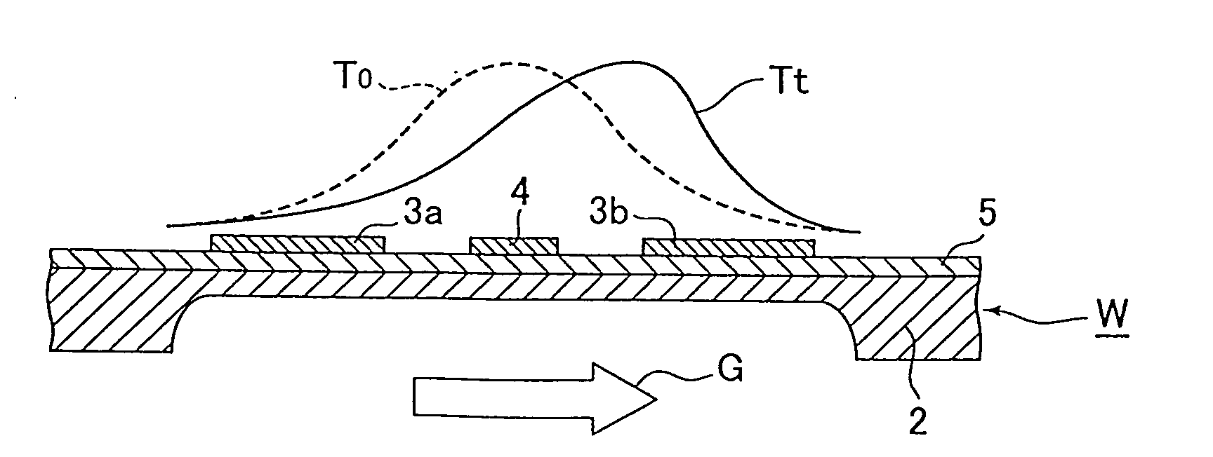
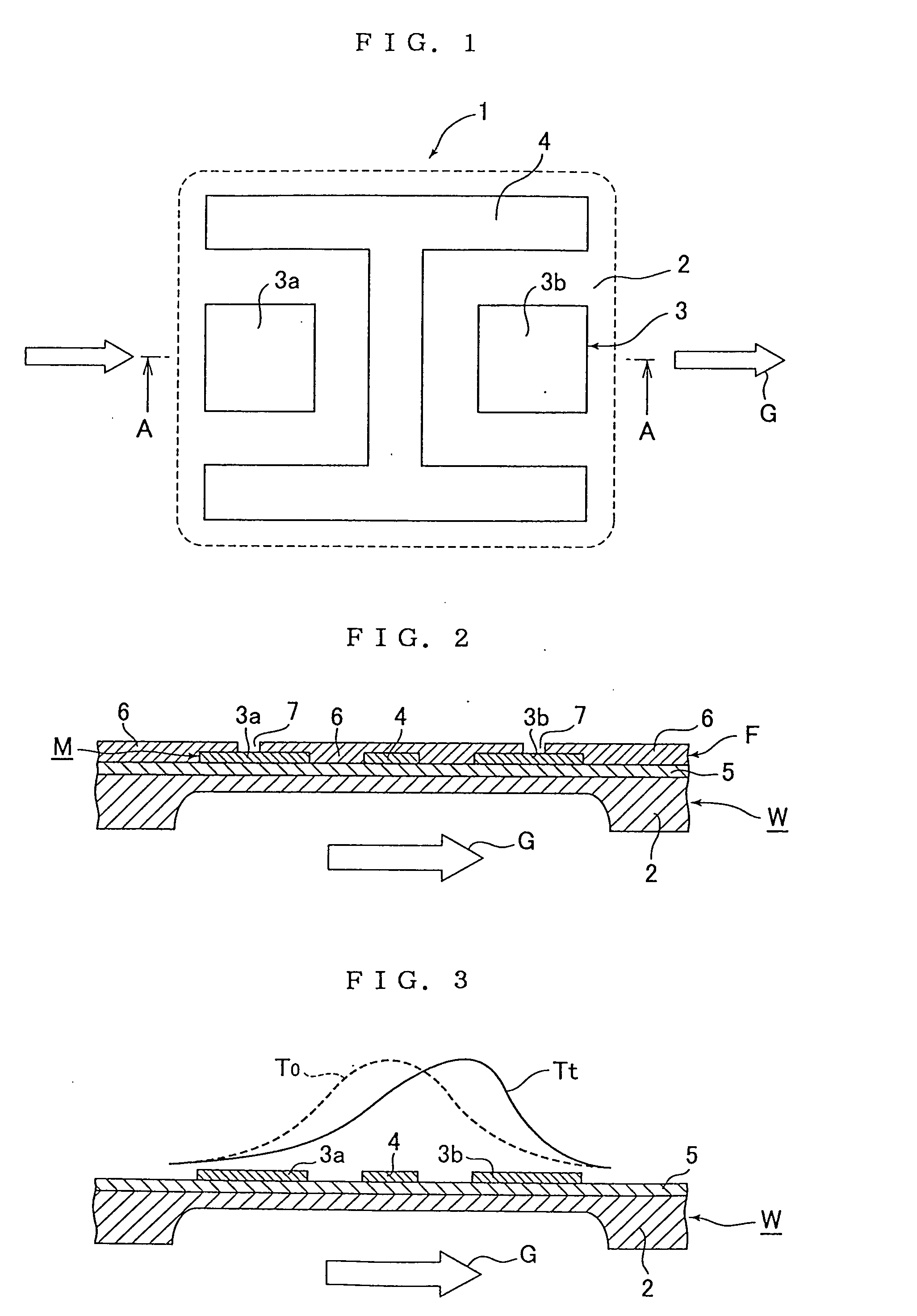
[0089]FIG. 1 is a plan schematic view of the sensor part 1 which is an essential part of a corrosion resistant metal made thermal type mass flow rate sensor according to the present invention. FIG. 2 is a cross-sectional schematic view taken on line A-A of FIG. 1.

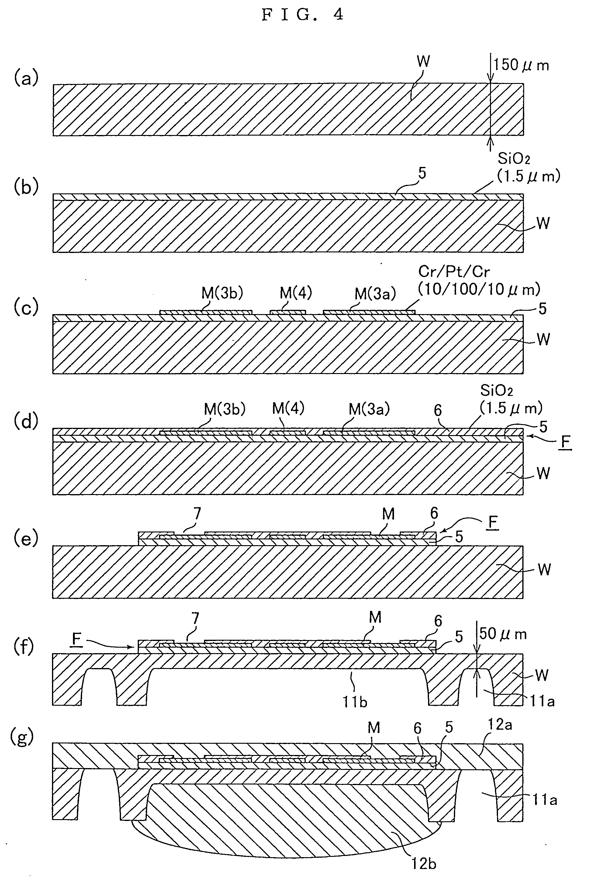
[0090] The said sensor part 1 comprises a thin heat resistant metal substrate 2, an insulation film 5 formed on the upper face of the substrate 2, a temperature sensor 3 and a heater 4 formed on the upper face of the insulation film 5, and a protection film 6 formed on the upper faces of the temperature sensor 3, a heater and the like. That is, the part which forms the sensor part 1 of the corrosion resistant metal material W with thickness of 120˜180 μm ( or a heat resistant metal substrate 2) is made to be a thin plate with thickness of approximately 30˜80 μm, as described later, by removing a part of the...


PUM

PropertyMeasurementUnit
thicknessaaaaaaaaaa
thicknessaaaaaaaaaa
thicknessaaaaaaaaaa

Abstract

A corrosion resistant thermal type mass flow rate sensor, and a fluid supply device employing the sensor, are provided thus allowing enhanced corrosion resistance of the thermal type mass flow rate sensor, improve responsiveness, to be achieved particle-free, and to prevent unevenness of product qualities. A thermal type mass flow rate sensor is constituted with a sensor part 1 comprising a corrosion resistant metal substrate 2 formed as a thin plate by applying electrolytic etching on the rear face side of a corrosion resistant metal material W, thin film F forming a temperature sensor 3 and a heater 4 mounted on the rear face side of the corrosion resistant metal substrate 2, and a sensor base 13 hermetically fitted by welding to the outer periphery of the corrosion resistant metal substrate 2 of the afore-mentioned sensor part 1 fitted into a fixture groove 13a.

Description

FIELD OF THE INVENTION [0001] The present invention is employed mainly to detect a mass flow rate in a gas supply line and the like with semiconductor manufacturing facilities, and is concerned with a corrosion resistant metal made thermal type mass flow rate sensor and a fluid supply device for which the sensor is employed, of which all the gas contacting faces are formed of corrosion resistant metals such as stainless steel (SUS316L) and the like having excellent corrosion resistance even to highly corrosive fluids, enabling to achieve to make it particle-free and leak-free. BACKGROUND OF THE INVENTION [0002] Conventionally, a capillary thermal type mass flow rate sensor or a silicon-made ultra-small-sized thermal type mass flow rate sensor by making use of micro-machine technologies has been widely used to measure a mass flow rate of a liquid in the technical fields such as chemical analysis equipment and the like. [0003] The former, or a capillary thermal type mass flow rate sen...

Claims


Application Information

Patent Timeline
Patent Type & Authority Applications(United States)
IPC IPC(8): G01F1/68G01F1/692G01F1/684
CPCG01F1/6845G01F1/68
Inventor IKEDA, NOBUKAZUHIRATA, KAORUNISHINO, KOUJIDOHI, RYOUSUKE
Owner FUJIKIN INC
Why Eureka
Try Eureka