Acceleration sensor

a sensor and acceleration technology, applied in the field of acceleration sensors, can solve the problems of sensor shock resistance reduction in the time of sensor falling, unanticipated power supply, and undesirable electrical improvement, so as to improve the shock resistance, and improve the effect of width

Inactive Publication Date: 2006-03-16
HOSIDEN CORP
View PDF3 Cites 11 Cited by
  • Summary
  • Abstract
  • Description
  • Claims
  • Application Information

AI Technical Summary

Benefits of technology

[0031] Where both the outer track and inner track are formed parts of circular tracks, the vibrating portion is formed more close to circular to suppress a difference in output between the X- and Y-directions. The outer track and inner track are connected by a curved or S-shaped connecting track. Compared with the case of each elastic support portion having an angled connection between the vibrating portion and fixed portion, a force acting on the above connection may be distributed to avoid its concentration. Thus, even when an excessive shock is applied to the acceleration sensor as by falling, for example, the diaphragm is less likely to be damaged and has improved shock resistance.
[0032] If the slits were formed simply narrow and linear, a strong force acting on the slits could break the slits per se, or the slits could fail to absorb such a strong force, thereby distorting the diaphragm. The reaction from the case is dynamically the most intensive in the directions perpendicular to the tangents at the points of contact noted above. Where the slits have the semicircular cutouts bulging in the same directions as the projections, the slits have an increased width in the above directions perpendicular to the tangents at the points of contact. As a result, the slits can demonstrate yield strength against an increased reaction.
[0033] The acceleration sensor can obtain an output with advantage where the diaphragm has a great mechanical amplitude resulting from acceleration applied. On the other hand, there is a drawback of being damaged when subjected to an excessive shock such as a fall. The diaphragm is not formed of PET (polyethylene terephthalate) or PPS (polyphenylene sulfide) film, but formed of a material having high flexural strength such as SK material (carbon tool steels: JIS G 4401), stainless steel, phosphor bronze, Be—Cu, Ti—Cu or the like. In this way, the diaphragm itself may be given increased strength. The connection between the diaphragm and weight may be achieved by adhesion, electric welding, laser spot welding, calking, etc.

Problems solved by technology

However, when used as a pedometer, for example, the sensor is in many cases battery-driven, and naturally, abundant power supply cannot be expected.
It is therefore undesirable to improve sensitivity electrically by using an IC (integrated circuit) for amplification which will consume a large amount of current.
However, when the amplitude of the movable electrode is increased in order to increase the force of inertia, the sensor will have reduced shock resistance in time of falling of the sensor.
It is therefore difficult for the basic structure alone shown in Document 1 to cope fully with these problems.

Method used


Image

  • Acceleration sensor
  • Acceleration sensor
  • Acceleration sensor

Examples


Embodiment Construction

[0038] A preferred embodiment of the acceleration sensor according to the present invention will be described hereinafter with reference to the drawings.

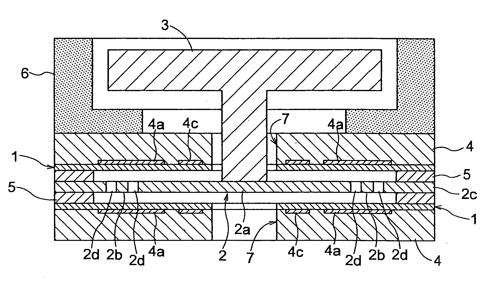
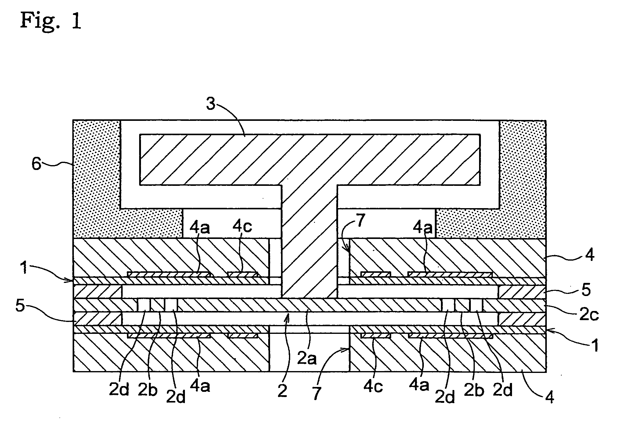
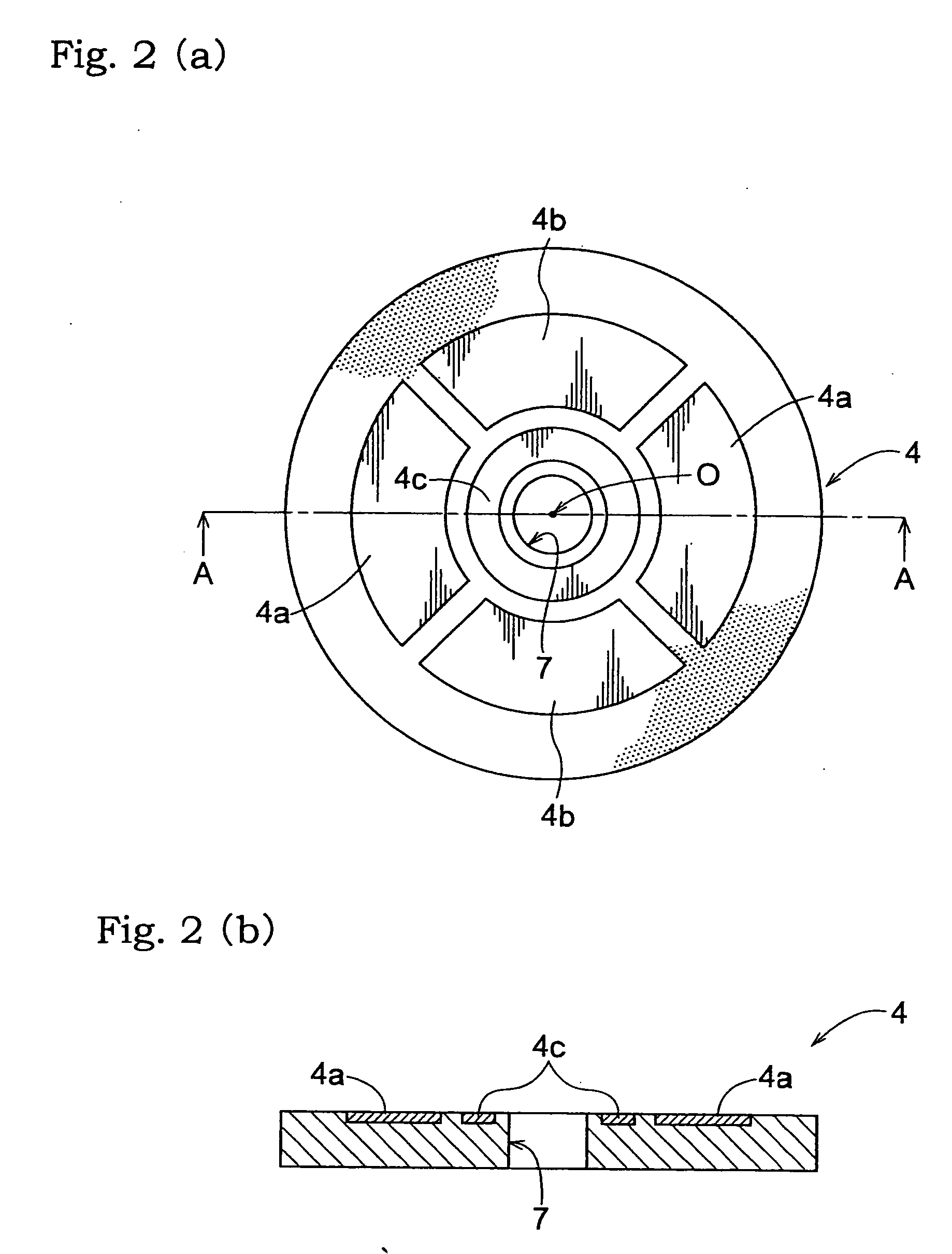
[0039] The acceleration sensor according to the invention includes a conductive case of channel-shaped section having a bottom at one end, and an opening at the other end, and a capacitance detecting mechanism of the electret condenser microphone (ECM) type mounted in the case as shown in FIG. 1. As shown in FIG. 1, the sensor has a push-pull type construction including an electrode substrate pair having two electrode substrates 4, each with fixed electrodes arranged on one surface, covered by an electret layer 1, and opposed to the fixed electrodes on the other substrate 4, a diaphragm 2 acting as a movable electrode held between the electrode substrate pair by spacers 5 for providing a predetermined distance from the electrode substrate pair, and a weight 3 attached to the diaphragm 2 with the center of gravity of the weight 3 co...


PUM


Abstract

A three-axis acceleration sensor having a simple construction is provided for improving shock resistance without lowering sensor sensitivity.
An acceleration sensor for detecting acceleration in three orthogonal directions comprises an electrode substrate pair including electrode substrates (4) opposed to each other, and each having fixed electrodes (4c, 4b, 4a) corresponding to three axes, respectively, a diaphragm (2) acting as a movable electrode, and an umbrella-like weight (3) mounted centrally of the diaphragm (2).
Acceleration is detected based on variations in capacitance between the fixed electrodes (4c, 4b, 4a) and diaphragm (2).
Each electrode substrate (4) has an electret layer (1) formed to cover surfaces of the fixed electrodes (4c, 4b, 4a). At least one of the electrode substrates defines, centrally thereof, a through hole (7). A shaft portion of the umbrella-like weight (3) extends through the through hole (7) from outside, and is connected to the diaphragm (2).

Description

BACKGROUND OF THE INVENTION [0001] 1. Field of the Invention [0002] The present invention relates to an acceleration sensor for detecting acceleration in three orthogonal directions. [0003] 2. Description of the Related Art [0004] Various acceleration sensors have been proposed for detecting acceleration in three-dimensional directions, i.e. along X-axis, Y-axis and Z-axis. Japanese patent application “Kokai” No. 10-10150 cited herein as Document 1 (FIGS. 1 to 3, and paragraphs 7 to 22), for example, discloses an acceleration sensor for detecting acceleration based on variations in capacitance between a fixed electrode and a movable electrode opposed to each other. According to this technique, one of the fixed electrode and movable electrode has an electret film formed on a surface thereof opposed to the other electrode. The movable electrode has a weight attached to a surface thereof facing away from the fixed electrode to allow for displacement of the movable electrode in time of ...

Claims


Application Information

Patent Timeline
Patent Type & Authority Applications(United States)
IPC IPC(8): G01P15/00G01P15/125G01P15/18
CPCF16F1/326G01H11/06G01P15/18G01P15/125G01P1/023G01P15/00
Inventor YAMAMOTO, AKIRASUGIMORI, YASUO
Owner HOSIDEN CORP
Why Eureka
Try Eureka