Polishing apparatus, polishing head and polishing method

a polishing head and polishing technology, applied in the direction of grinding drives, manufacturing tools, lapping machines, etc., can solve the problems of difficult production of a presser ring perfectly parallel to the abrasive cloth b>54, difficult to form the minute patterns of a circuit, and excessive polishing of the peripheral parts of the wafer, etc., to prevent the production of polished wafers, improve the flatness of the edge part of the wafer, and reduce the cost of apparatus

Inactive Publication Date: 2006-03-16
SUMCO TECHXIV
View PDF18 Cites 5 Cited by
  • Summary
  • Abstract
  • Description
  • Claims
  • Application Information

AI Technical Summary

Benefits of technology

[0024] By virtue of the fact that, based on the abovementioned disclosed inventions, the abovementioned retainer ring and the abovementioned chuck can be independently pressurized at the optimum pressure and, moreover, they can mutually oscillate, a wafer polishing apparatus and polishing method therefor that facilitates the improvement of the flatness of the wafer edge part in the coarse polishing used for engendering flatness and prevents the production of a polished wafer of an asymmetric shape can be produced.
[0025] In addition, based on the present inventions, because the polishing in the abovementioned coarse polishing step is implemented in a state in which the abovementioned abrasive cloth is pushed by the abovementioned retainer ring and the polishing in the abovementioned final polishing step is implemented in a state in which the abovementioned retainer ring is retracted from the abovementioned abrasive cloth, the abrasive grain used for the coarse polishing is not introduced into the final polishing stage. In addition, due to the continuous implementation of the coarse polishing and the final polishing using the same polishing head, a reduction in apparatus costs can be achieved.
[0026] Furthermore, based on the present inventions, because the abovementioned retainer ring can be relatively rotated with respect to the abovementioned wafer chuck, a worsening of wafer flatness that has its origin in the processing precision of the abovementioned retainer ring and eccentric wear of the abovementioned retainer ring can be prevented by this rotating mechanism.

Problems solved by technology

A low level of wafer surface flatness generates a problem whereby, because of the partial lack of focus of the lens focal point that occurs during exposure in the photolithography step, the formation of the minute patterns of a circuit is difficult.
When this happens, because of the concentration of elastic stresses from the abrasive cloth on the edge of the wafer, the pressure applied to the wafer is larger at the peripheral part than the center part and results in the excess polishing of the peripheral part of the wafer.
However, in actual practice the production of a presser ring 52 that is perfectly parallel to the abrasive cloth 54 is very difficult.

Method used


Image

  • Polishing apparatus, polishing head and polishing method
  • Polishing apparatus, polishing head and polishing method
  • Polishing apparatus, polishing head and polishing method

Examples


embodiment 1

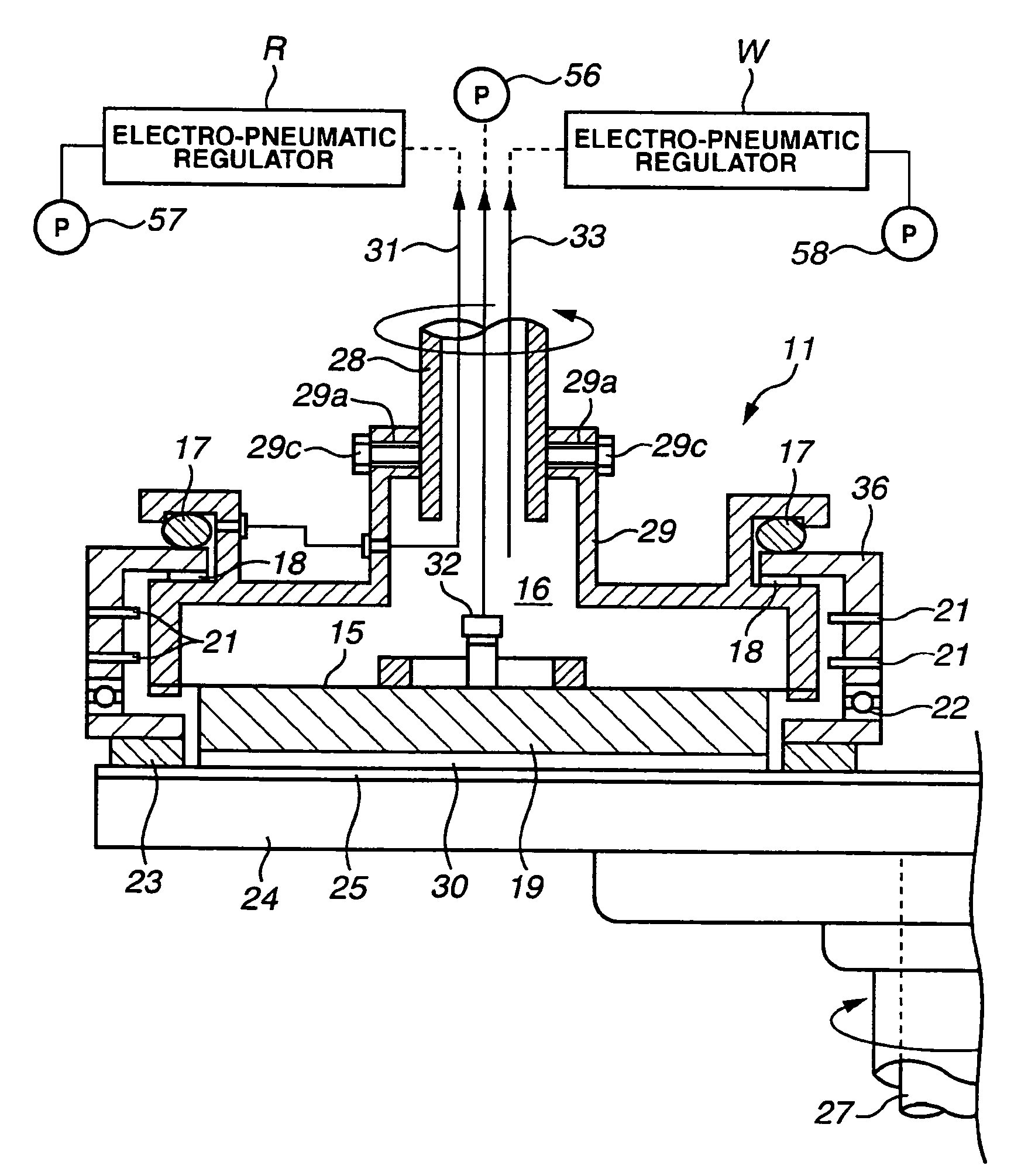
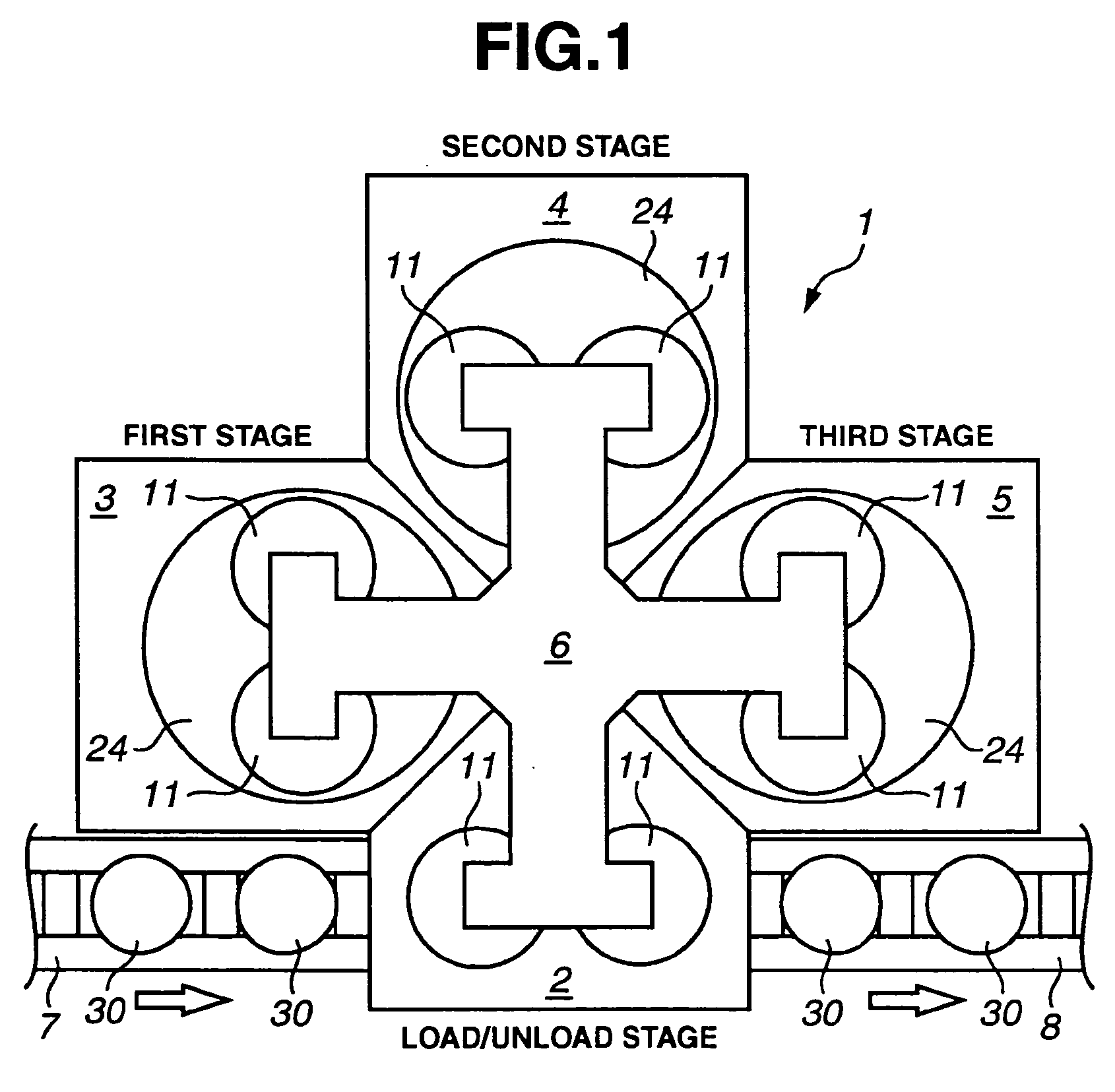
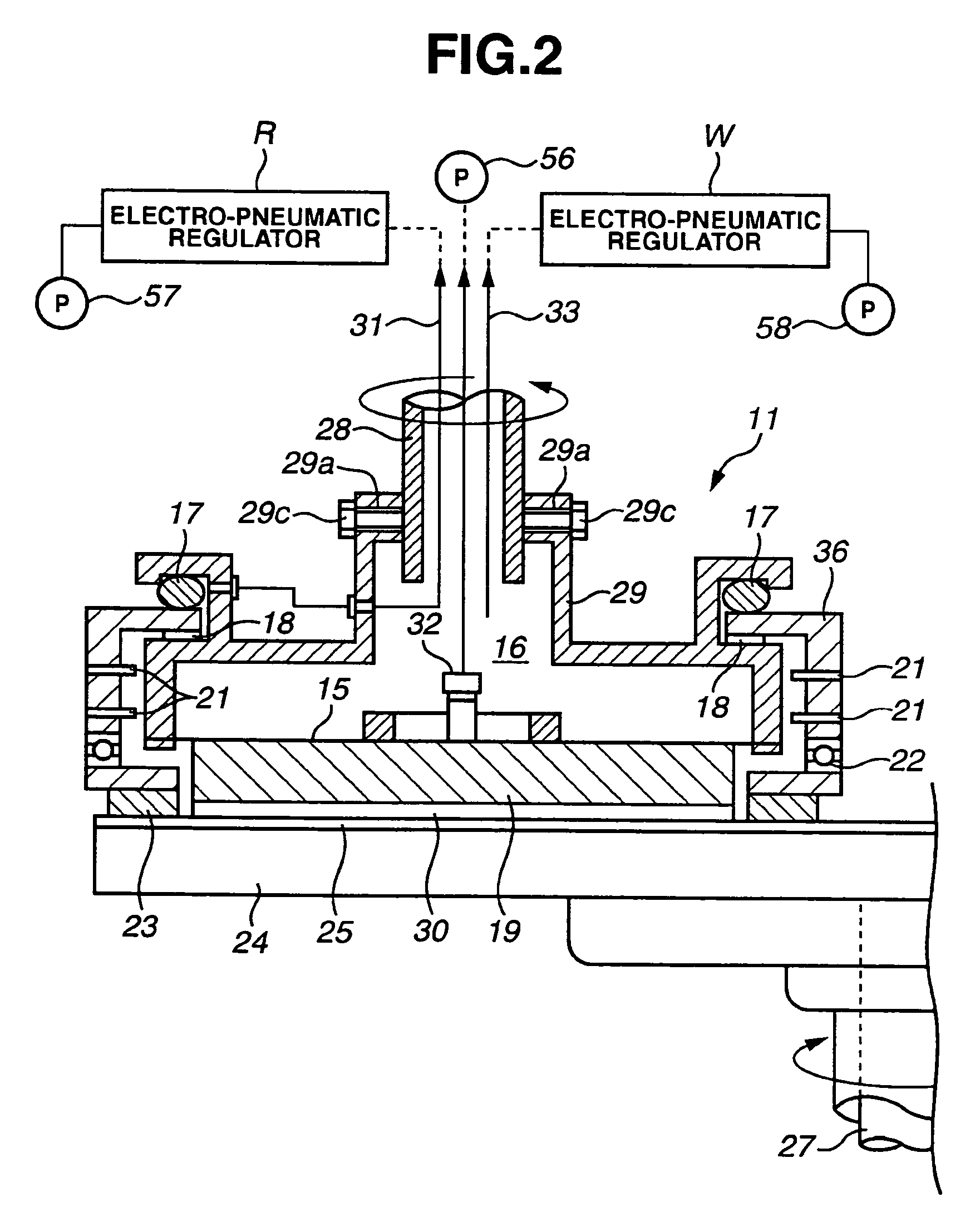
[0041] First, a description will be given of a first embodiment with reference to FIG. 1 to FIG. 3. FIG. 1 is a full block diagram of a wafer polishing apparatus of the present invention, FIG. 2 is a cross section of a first stage 3 and a second stage 4 of an airbag pressure-type polishing head 11 pertaining to this embodiment, and FIG. 3 is a vertical cross section of a third stage 5 of the airbag pressure type polishing head 11 pertaining to this embodiment.

[0042] First, a brief description of the constitution of the wafer polishing apparatus as a whole will be given with reference to FIG. 1. FIG. 1 is a plan view of a polishing apparatus I comprising the polishing head 11 of the present invention that comprises first to third stages 3, 4 and 5 and a wafer load / unload stage 2.

[0043] The first stage 3 and second stage 4 form a coarse polishing step and the third stage 5 forms a final polishing step, the coarse polishing step being provided to control the removal of the processing...

embodiment 2

[0080] Next, a description will be given of a second embodiment with reference to FIG. 4 and FIG. 5. FIG. 4 is a vertical cross section of a first stage 3 and a second stage 4 of a bellows pressure-type polishing head 40 pertaining to a second embodiment of the present invention, and FIG. 5 is a vertical cross section of the third stage 5 of the bellows pressure-type polishing head 40 pertaining to this embodiment.

[0081] Because the overall constitution of this embodiment is identical to the overall constitution of the first embodiment shown in FIG. 1, the description is given with reference to FIG. 4 and pertains only to the points of difference of the constitution of the polishing head 40. FIG. 4 is a vertical cross section of the polishing head 40 fixed to the end of the polishing head support part 6 and a polishing plate 24 arranged there-below and, although, for the convenience of the description, only the left half of one polishing head 40 and polishing plate 24 is shown, an ...

embodiment 3

[0116] Next, a description will be given of a third embodiment with reference to FIG. 9 and FIG. 10. FIG. 9 and FIG. 10 are vertical cross sections of a dual series airbag system polishing head 60 pertaining to a third embodiment of the present invention. FIG. 9 shows a state in which the retainer is lowered and FIG. 10 shows a state in which the retainer is lifted.

[0117] The dual series airbag system polishing head 60 comprises a shaft 68, frame 69, wafer chuck 19, retainer frame 66 and retainer ring 23 and the like. The symbol 68 in the diagram refers to a cylindrical hollow shaft, and a frame 69 is fixed to the periphery of the shaft 68.

[0118] A toroidal retainer-fixing piece 70 is fastened to the top of the retainer ring 23 by a bolt 71. The retainer-fixing piece 70 is further fastened to a retainer frame 66 by a bolt 72. A flexible plate spring 74 and plate rubber 73 are tensioned between the retainer-fixing piece 70 and the retainer frame 66, and a second airbag 75, formed a...


PUM

PropertyMeasurementUnit
distanceaaaaaaaaaa
thicknessaaaaaaaaaa
outer diameteraaaaaaaaaa

Abstract

A polishing apparatus comprises a polishing plate (24), an abrasive cloth (25) attached to the surface of the polishing plate (24), a chuck (19) for holding and pressing one surface of a wafer (39) against the abrasive cloth (25), and a circular retaining ring (23) concentrically arranged on the periphery of the chuck (19). The retaining ring (23) is rotatable and vertically movable with respect to the chuck (19), and is pressed against the abrasive cloth (25) during the lapping step. The retaining ring (23) is lifted upward during the final polishing step, thereby preventing lapping grains from being brought into the final polishing stage. Accordingly, lapping and final polishing can be successively conducted using the same polishing head. With this structure, cost cutting of the apparatus can be realized, since lapping and final polishing are successively conducted using the same polishing head without bringing the lapping grains used for lapping into the final polishing stage.

Description

TECHNICAL FIELD [0001] The present invention relates to the manufacture of a semiconductor wafer or liquid crystal substrate or the like, and more particularly relates to an apparatus and polishing head for polishing the surface of a polishing target material comprising a flat surface such as a semiconductor wafer or liquid crystal substrate, and the method for the polishing thereof. [0002] Herein, the term “final polishing” refers to the final polishing step of the polishing steps implemented in the manufacture of a wafer, and the term “coarse polishing” refers to polishing steps other than for final polishing. BACKGROUND ART [0003]FIG. 7 is a flow diagram illustrating the normal steps involved in the manufacture of a mirror-surface wafer of the prior art. With reference to the diagram, a general description will be given of a normal method for the manufacture of a mirror-surface wafer employed as a raw material wafer for the production of a semiconductor devices. [0004] First, a s...

Claims


Application Information

Patent Timeline
Patent Type & Authority Applications(United States)
IPC IPC(8): B24B1/00B24B37/04B24B37/30B24B37/32H01L21/304
CPCB24B37/30
Inventor KITAHASHI, MASAMITSUKAMEI, TOSHIYUKITAKEDA, HIDETOSHITOKUNAGA, HIROYUKITAJIRI, TOMOAKI
Owner SUMCO TECHXIV
Why Eureka
Try Eureka