Process for manufacturing hybrid components as well as components manufactured according to this process

a technology of hybrid components and manufacturing processes, applied in the direction of coatings, etc., can solve the problems of inability to manufacture hybrid components, high cost, complicated process, etc., and achieve the effect of low melting point, high melting point, and high pressur

Inactive Publication Date: 2006-03-23
HANS HUONKER
View PDF10 Cites 18 Cited by
  • Summary
  • Abstract
  • Description
  • Claims
  • Application Information

AI Technical Summary

Benefits of technology

[0023] These injection-moldable hot melt adhesives are characterized in that they have, in particular, an especially low melting point, so that the electronic components cannot be damaged during extrusion coating. In addition, these hot melt adhesives contain no abrasive substances, by which the surfaces of the electronic components could be damaged during the extrusion coating of the electronic components. The pressure is also extremely low during the injection molding operation in case of such injection-moldable hot melt adhesives, so that destruction of the electronic component due to pressure cannot occur, either.
[0024] This component, comprising the premolding with the electronic component as well as the component extrusion coated with the hot melt adhesive, is additionally extrusion coated now according to the present invention with a conventional, injection moldable plastic. A hybrid component can be manufactured by this procedure in a continuous injection molding process, in which the component is only manufactured in different, consecutive injection molding operations between the individual process steps. This is extremely inexpensive, on the one hand, and, on the other hand, an injection molding is made available, which has the required mechanical properties and at the same time also the necessary tightness, especially in the area of the electronic component.
[0025] Due to a corresponding embodiment of the premolding, to which the electronic component is attached, complete extrusion coating of the electronic component is also guaranteed, without any inclusions of air being able to be formed, as this happens during the conventional filling with a casting compound.
[0026] The “hot melt adhesive” is slightly “melted” on its surface during the subsequent extrusion coating, especially in the area of the “hot melt adhesive,” because of the higher pressure and the higher melting point of the plastic to be extrusion coated, so that a plastic mixture of the outer plastic and the hot melt adhesive is formed. To protect the electronic component against unacceptable thermal effects, provisions may be made for the mixed zone to have a distance of at least 0.5 mm from the electronic component. Additional tightness of the entire component is thus achieved as well.

Problems solved by technology

It was now found that the manufacture of hybrid components is extremely difficult when these are to additionally contain electronic components, which are likewise to be protected by a plastic against external effects.
However, since these electronic components are highly sensitive to external effects, e.g., high temperatures, moisture or even corrosive liquids, such as oil, brake fluid, etc., these electronic components must be protected by a corresponding housing.
The process described is thus extremely complicated and therefore expensive, but it has hitherto been necessary, because the electronic components cannot be extrusion coated with a conventional injection-moldable plastic.
This is not possible because, for example, the temperatures are on the order of magnitude of 350° C. during injection molding and the electronic components as well as the soldered joints would be damaged at such high temperatures during the injection molding operation and the hybrid component would thus be unfit for use.
In addition, conventional, injection-moldable plastics usually contain abrasive elements, so that, for example, the strip conductors on the surface of a board to be extrusion coated can also be damaged during the extrusion coating.

Method used


Image

  • Process for manufacturing hybrid components as well as components manufactured according to this process
  • Process for manufacturing hybrid components as well as components manufactured according to this process
  • Process for manufacturing hybrid components as well as components manufactured according to this process

Examples


Embodiment Construction

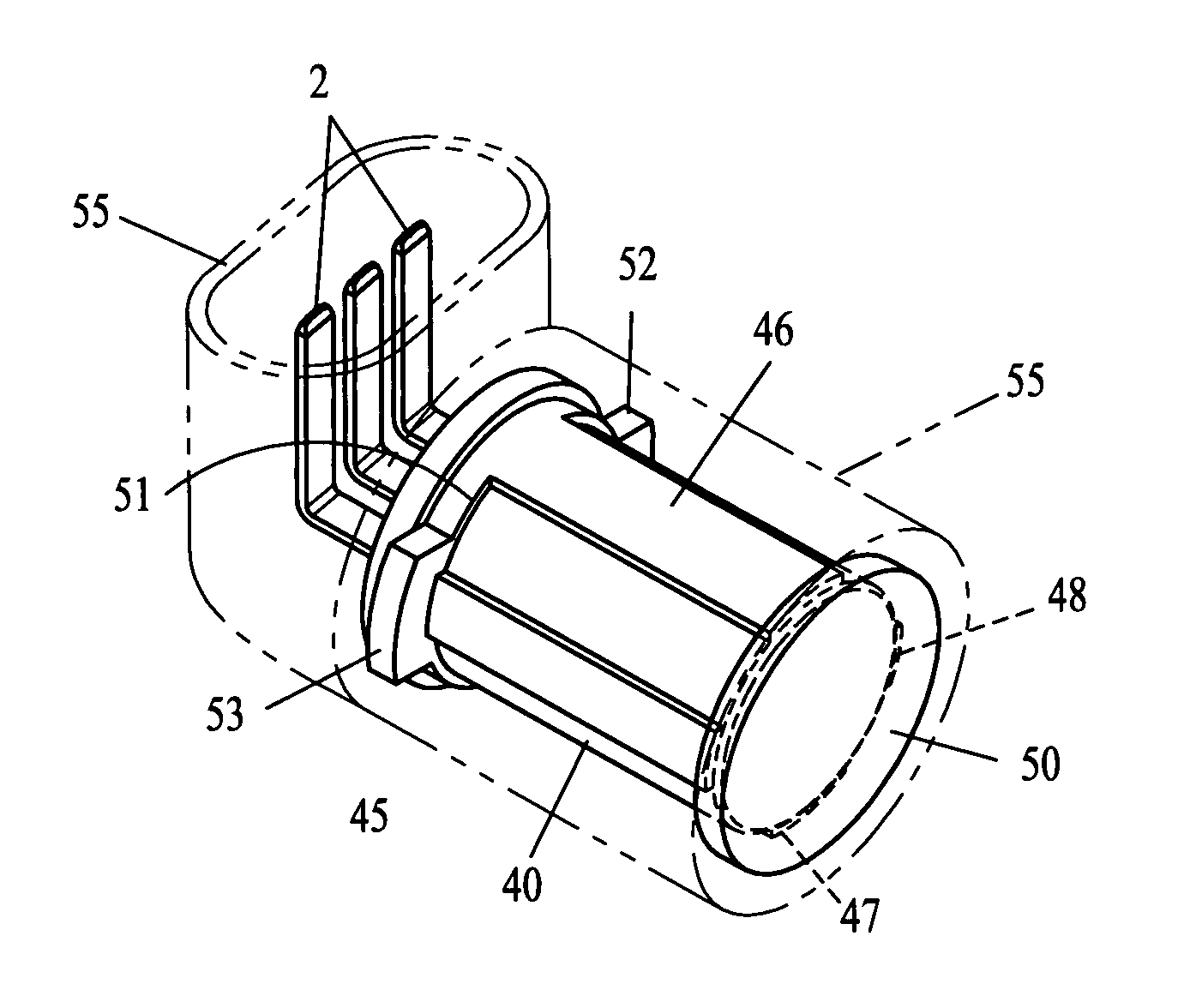
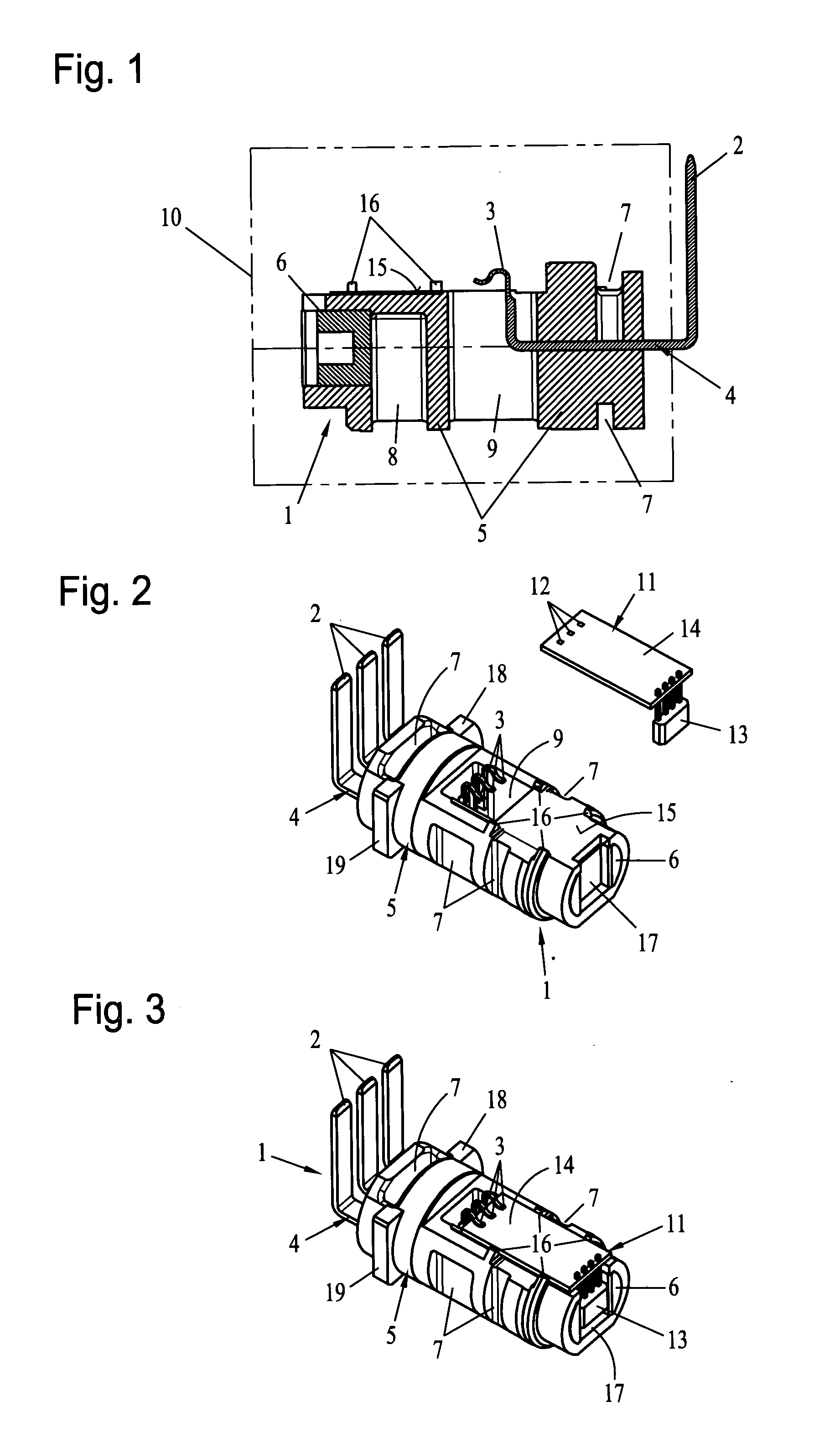
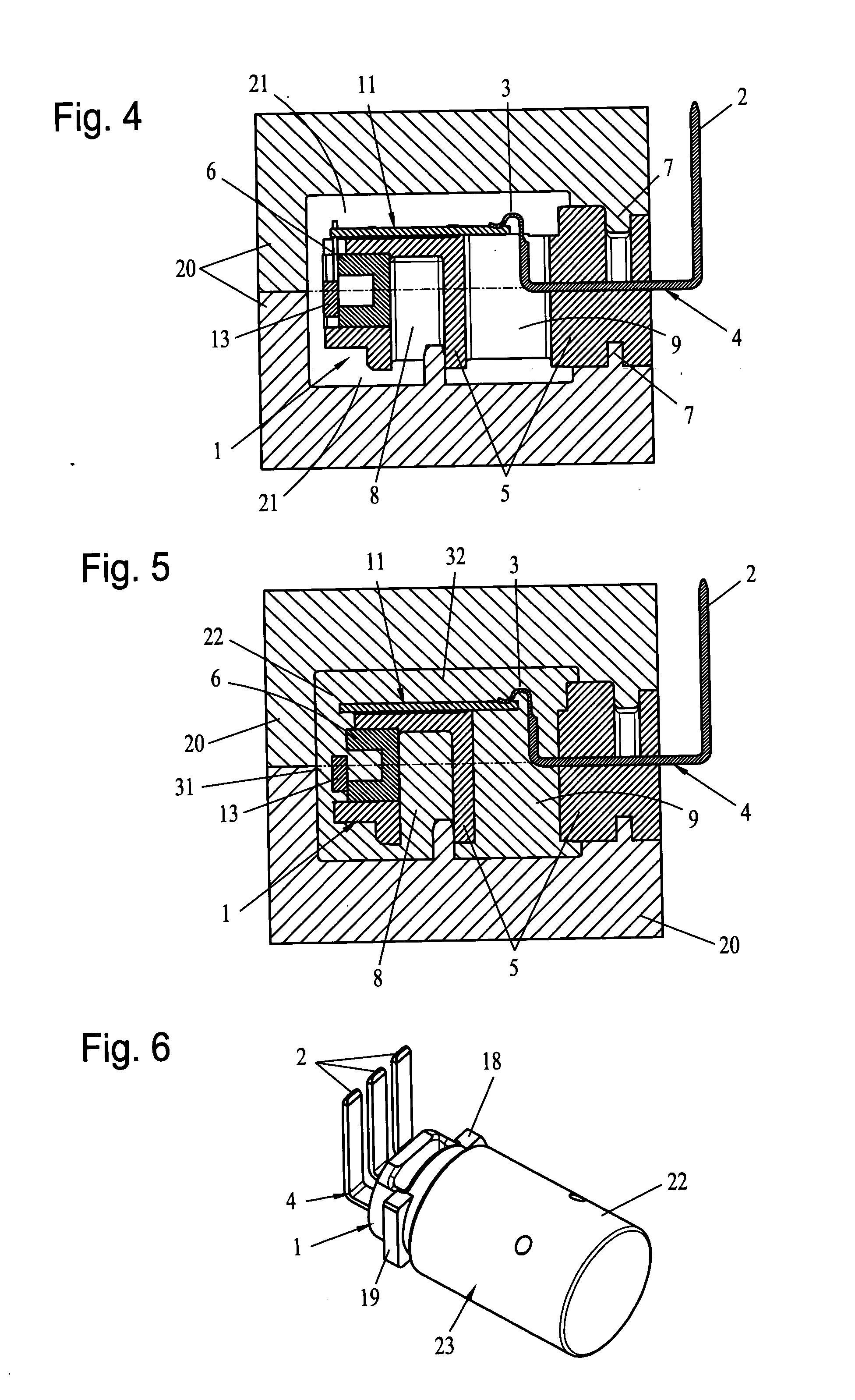
[0043] Referring to the drawings in particular, FIG. 1 shows a vertical section through a premolding 1, which is designed as a connection plug in this exemplary embodiment. The premolding 1 has a metal component 4 with a plurality of outer connection contacts 2 for this (FIG. 2), which are provided with inner connection elements 3 designed as terminal lugs. This premolding 1 is manufactured in an injection molding operation, in which the metal component 4 was partially extrusion coated with a plastic body 5. This plastic body 5 forms a basic body, in which, for example, a metal cooling element 6 is also embedded by molding in this exemplary embodiment on the left-hand side for cooling an electronic component.

[0044] Furthermore, it can be recognized from FIG. 1 that this basic body 5 has a plurality of depressions 7, 8 and recesses 9, so that an extremely small amount of plastic material is used to manufacture this basic body 5 by the injection molding operation. FIG. 1 also shows b...


PUM

PropertyMeasurementUnit
distanceaaaaaaaaaa
temperaturesaaaaaaaaaa
temperatureaaaaaaaaaa

Abstract

A process for manufacturing a hybrid component. To manufacture a hybrid component with electronic components in a possibly continuous manufacturing process, it is proposed according to the present invention that the electronic component be extrusion-coated with a hot melt adhesive melting at low temperature and to extrusion coat the intermediate product formed with a conventional plastic suitable for injection molding in an additional injection molding operation. On the one hand, damage to the electronic component is reliably prevented from occurring by this procedure, and, on the other hand, a hybrid component can be manufactured with a housing that is insensitive to external effects.

Description

CROSS REFERENCE TO RELATED APPLICATIONS [0001] This application claims the benefit of priority under 35 U.S.C. § 119 of German Application DE 10 2004 044 614.8 filed Sep. 13, 2004, the entire contents of which are incorporated herein by reference. FIELD OF THE INVENTION [0002] The present invention pertains to a process for manufacturing a hybrid component such as a metal and plastic component. BACKGROUND OF THE INVENTION [0003] Hybrid components are components formed of different materials, especially metal and plastic. For example, pre-profiled, strip-shaped pressed screens, which are wound off from a coil by means of a winder, are used to manufacture such components. Via a feed means, the pressed screen enters a combined bending and cutting machine, which has corresponding bending and cutting tools in order to prepare a pre-pressed and pre-bent sheet metal part to be introduced into an injection mold cavity. [0004] In other words, the strip-shaped pressed screen is a sheet metal ...

Claims


Application Information

Patent Timeline
Patent Type & Authority Applications(United States)
IPC IPC(8): B29C45/14
CPCB29C45/14639B29C45/1671B29C45/14836
Inventor HUONKER, HANS-GEORG
Owner HANS HUONKER
Why Eureka
Try Eureka